Review of Machine Works/Haynes' Jet Engine
By Dr Jennifer Martay PE, Course Leader for Medical Engineering at Anglia Ruskin University
I am a Biomedical Engineer, interested in continually increasing my knowledge of all things engineering. I did not learn about
mechanical engines previously so have been building kits to learn the part names and how the engines work. Previously, I gained
a lot of confidence using MachineWorks' Internal Combustion Engine
kit so I had high hopes for their jet engine kit.
What did I think about this kit?
I put this together with 3 small children one day during Half Term. Therefore, I didn't have much time to read the explanations in
the booklet while assembling the engine. The assembly instructions were very clear, but I did not feel like I learned
much until I went back and read the booklet later. The most learning came from reading the explanation booklet while
also watching the functioning jet engine. Now I feel confident with the part names and explaining the basics of how a
jet engine works.
In comparison to Machine Works' Internal Combusion Engine kit, the Jet Engine kit was a much faster build (2-3 hours vs 8-10
hours for the Internal Combustion Engine). The Jet Engine also had far fewer parts (>40 parts) than the Internal Combusion
Engine (>100 parts). Therefore, I wasn't sure why the Jet Engine kit wasn't significantly cheaper than the Internal
Combustion Engine kit. I bettered my understanding of Jet Engines so achieved my goal - but felt overcharged for the
experience.
For more details, watch the video below and/or keep reading!
First Impressions
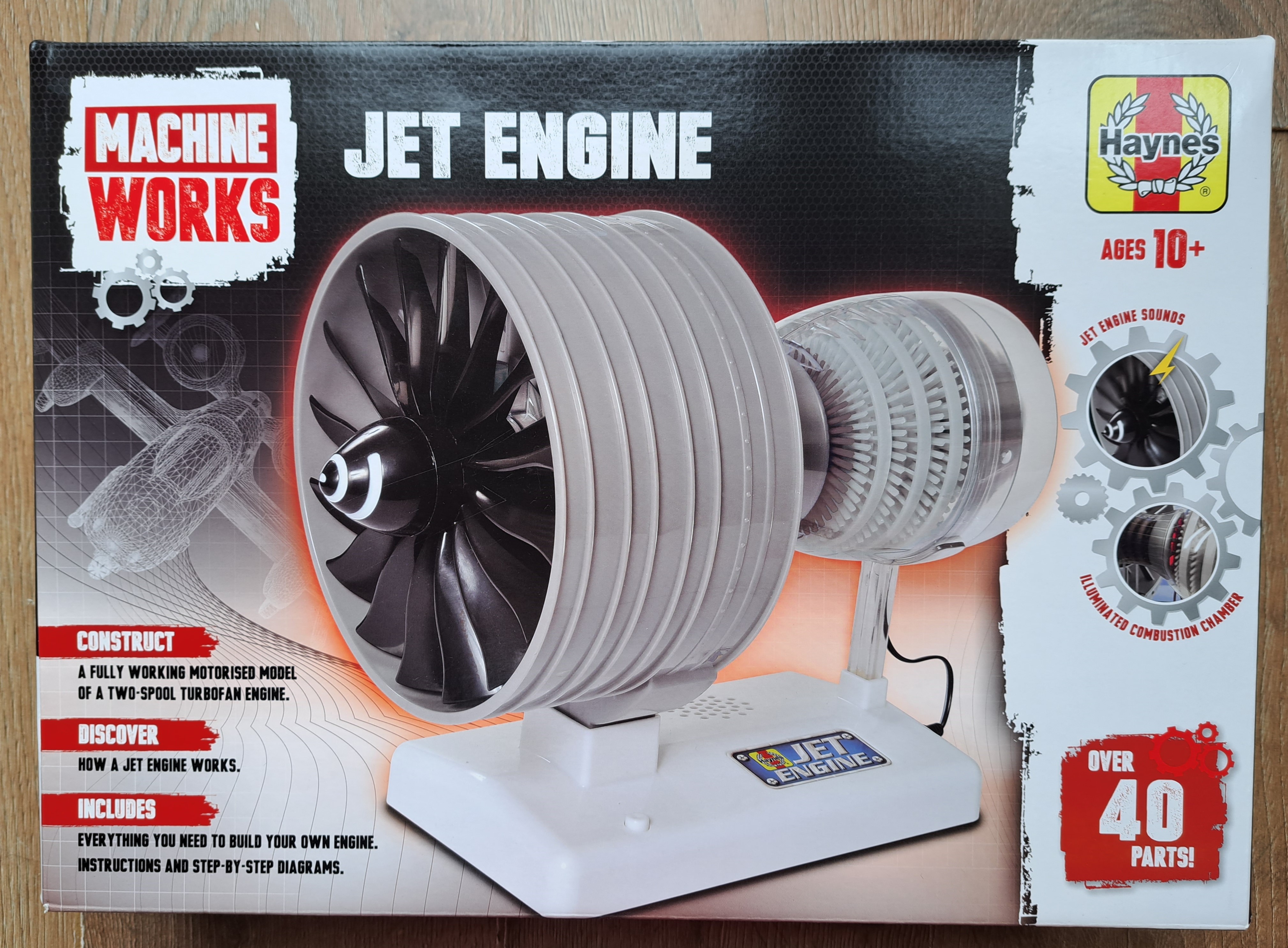
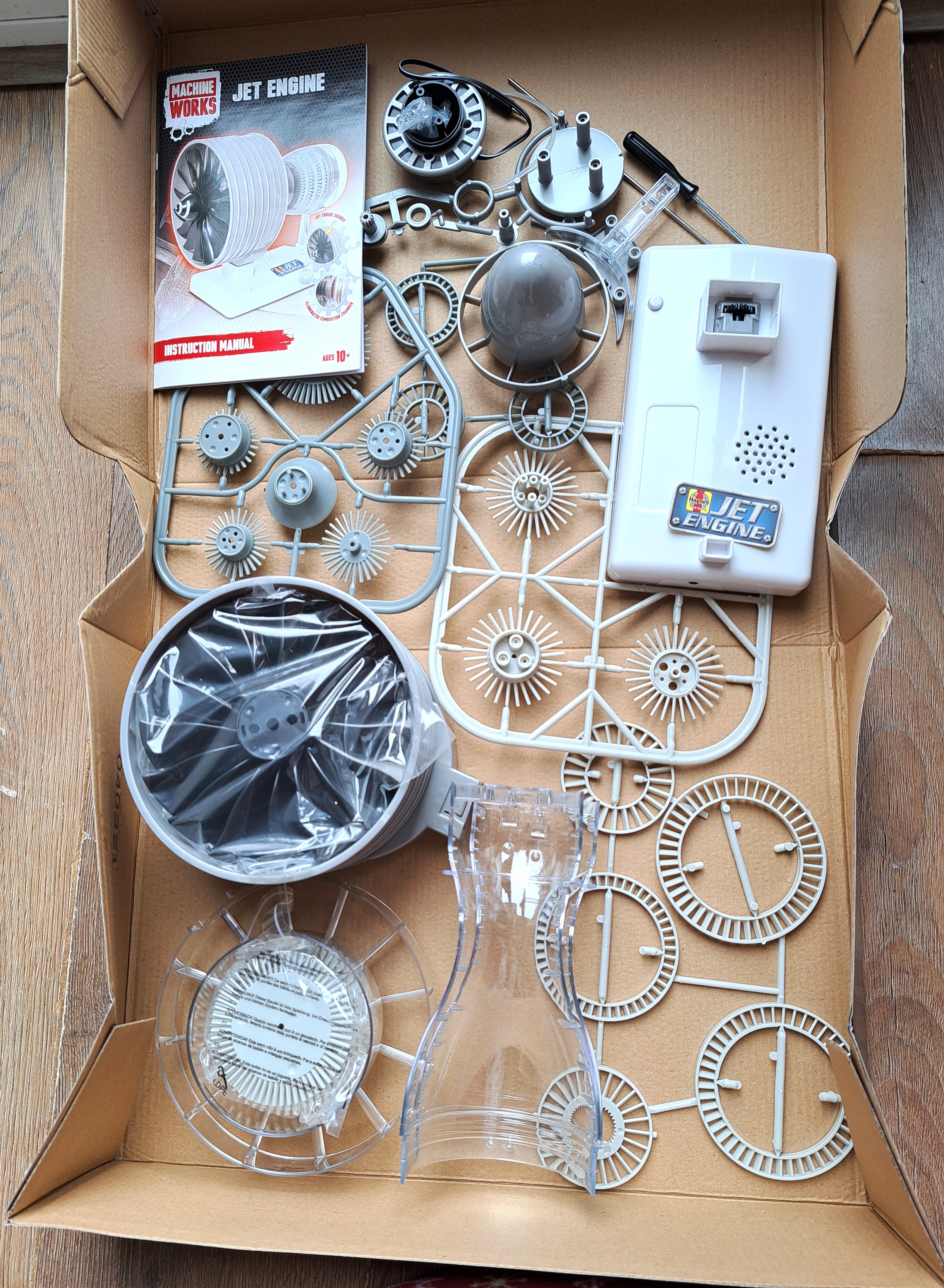
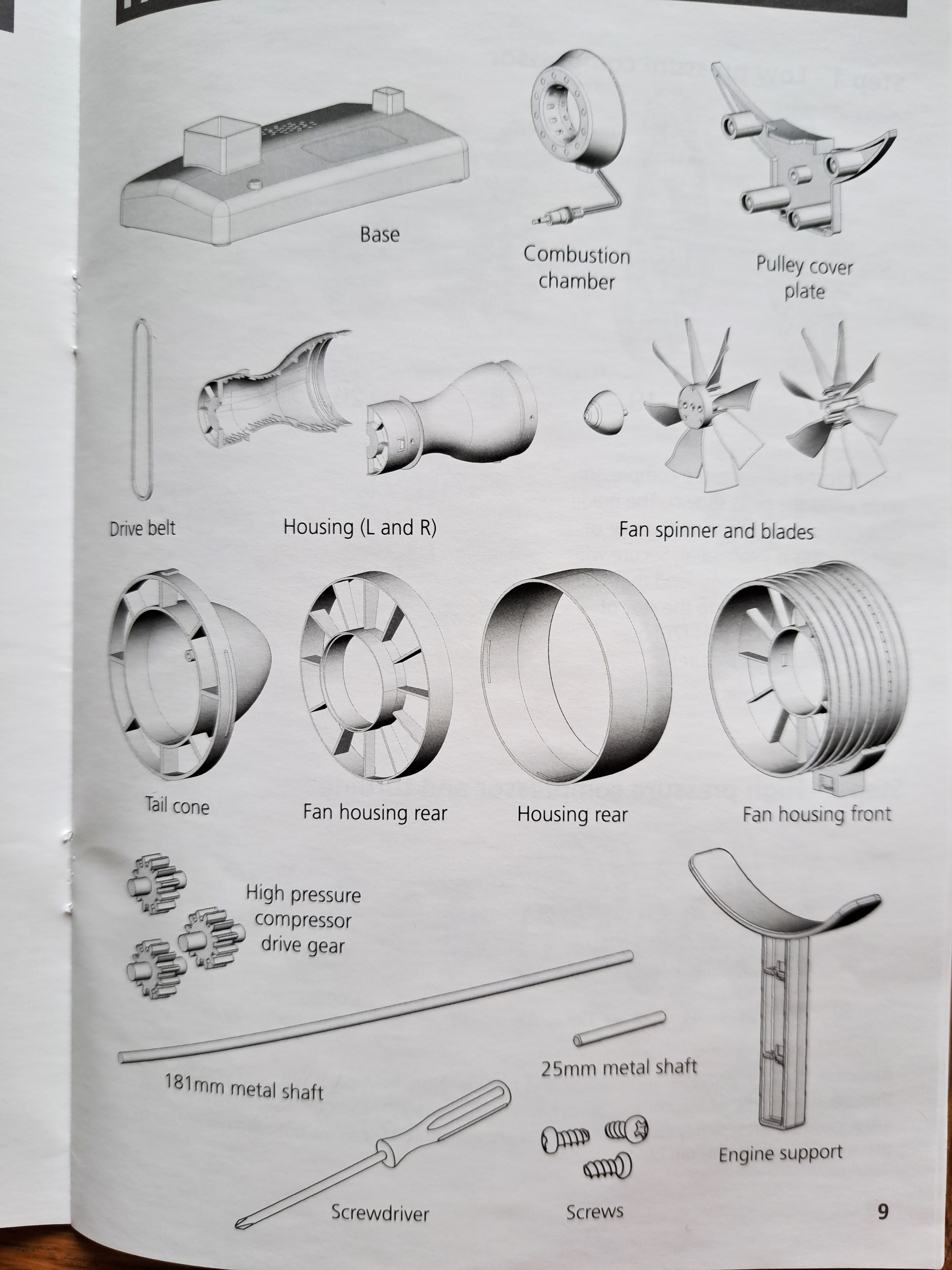
The kit comes with a booklet which names each part and shows step-by-step how to assemble the jet engine. All of the parts are clearly labelled both in the booklet and on the physical parts. Strangely, the parts come in many plastic bags, generally with only one plastic frame per bag. It seems it'd be cheaper and more environmentally-friendly to just provide the parts without the plastic bags? Overall, the kit looks like it will be fun to put together, although the kit is smaller and less involved than I expected for the £40 price point.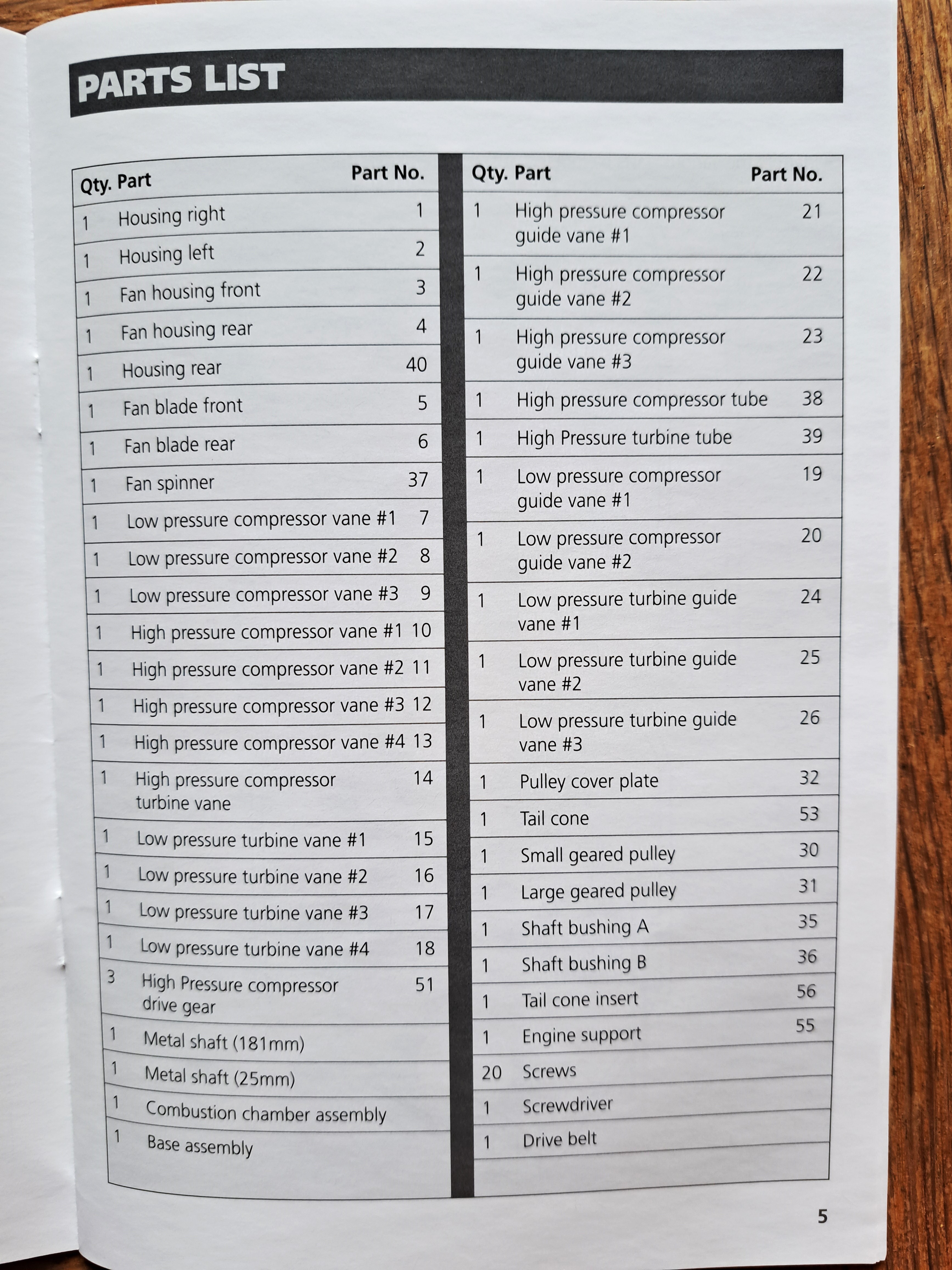
Overview of a Turbofan Jet Engine (based on explanation in booklet)
The ultimate purpose of a Jet Engine is to create thrust and allow a plane to fly. A Turbofan Jet Engine produces this thrust using a combination of a gas turbine with a Combustion Chamber ("Turbo")- and a fan/propeller ("Fan").Air first enters the nacelle through a fan. Some of the air simply moves through the nacelle. The rest of the air passes through the engine core (most of what we are building in this kit). The ratio of the air that goes around vs passes through the engine core is called the "bypass ratio".
The jet engine core in this kit has three regions (which slightly confusingly are made up of two spools): a Low Pressure Compressor, a High Pressure Compressor and Turbine, and a Low Pressure Turbine. The Low Pressure regions/spool have larger diameters (more room for air to spread out - hence being low pressure). Conversely, the High Pressure region/spool has smaller diameters (air is pushed together - hence being high pressure). The three regions are connected by a single, shared central shaft.
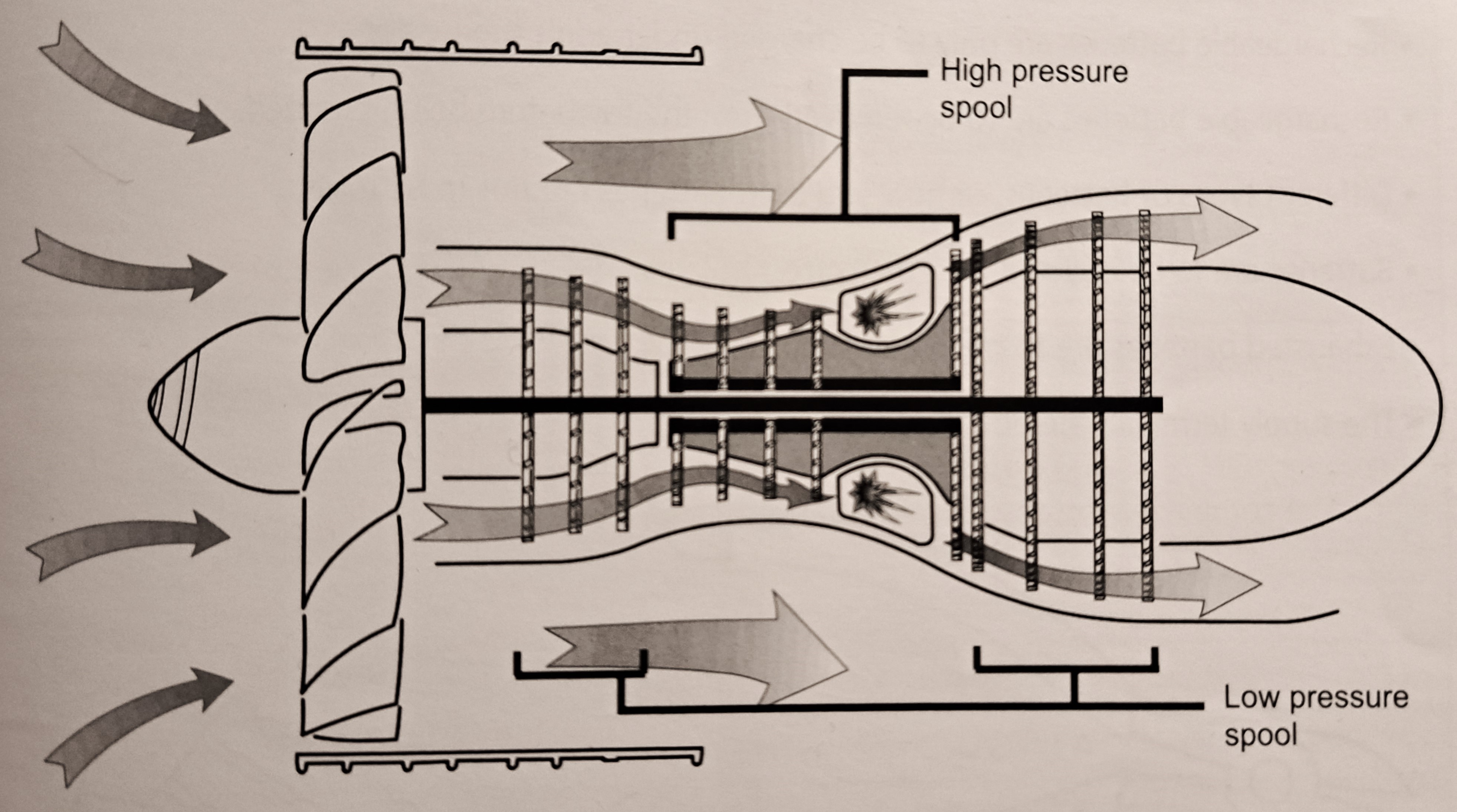
Stages within the Engine Core
1. The air that passes through the jet engine core first arrives in the relatively larger-diametered Low Pressure Compressor region.
2. The air then moves into the High Pressure Compressor and Turbine region, where the air is first compressed into a smaller and smaller area until the air reaches the Combustion Chamber.
3. Immediately after the Combusion Chamber, the diameter of the engine core increases again. This is the Low Pressure Turbine region. The moving air causes the turbines in this area to rotate - which, using the connecting shaft, causes the fan at the front of the engine to turn and draw in more air.
4. The air then moves out of the engine core and out of the nacelle.
Step 1: Building the Low Pressure Compressor
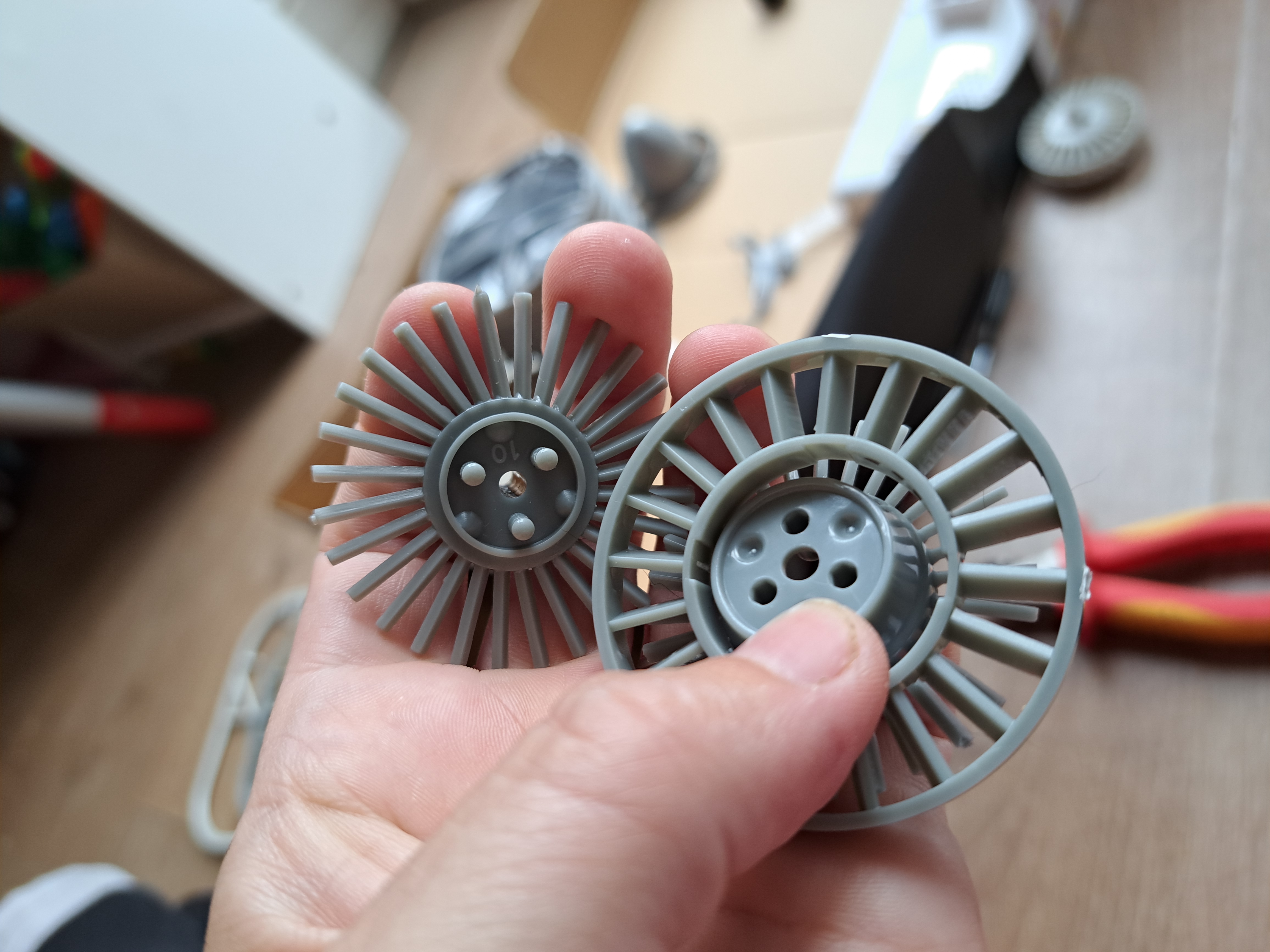
The Low Pressure Compressor is an alternating arrangement of compressor vanes (spokes coming out of the center, like a sun) and compressor guide vanes (hollow center with a ring of spokes towards the edges). Note, Guide Vanes have central rods and studs, which have part numbers on them. Remove the central rods and studs just before adding the Guide Vanes into the assembly. Otherwise, it's easy to mix the different parts up. The Vanes and Guide Vanes are held together by 3 screws and 3 drive gears.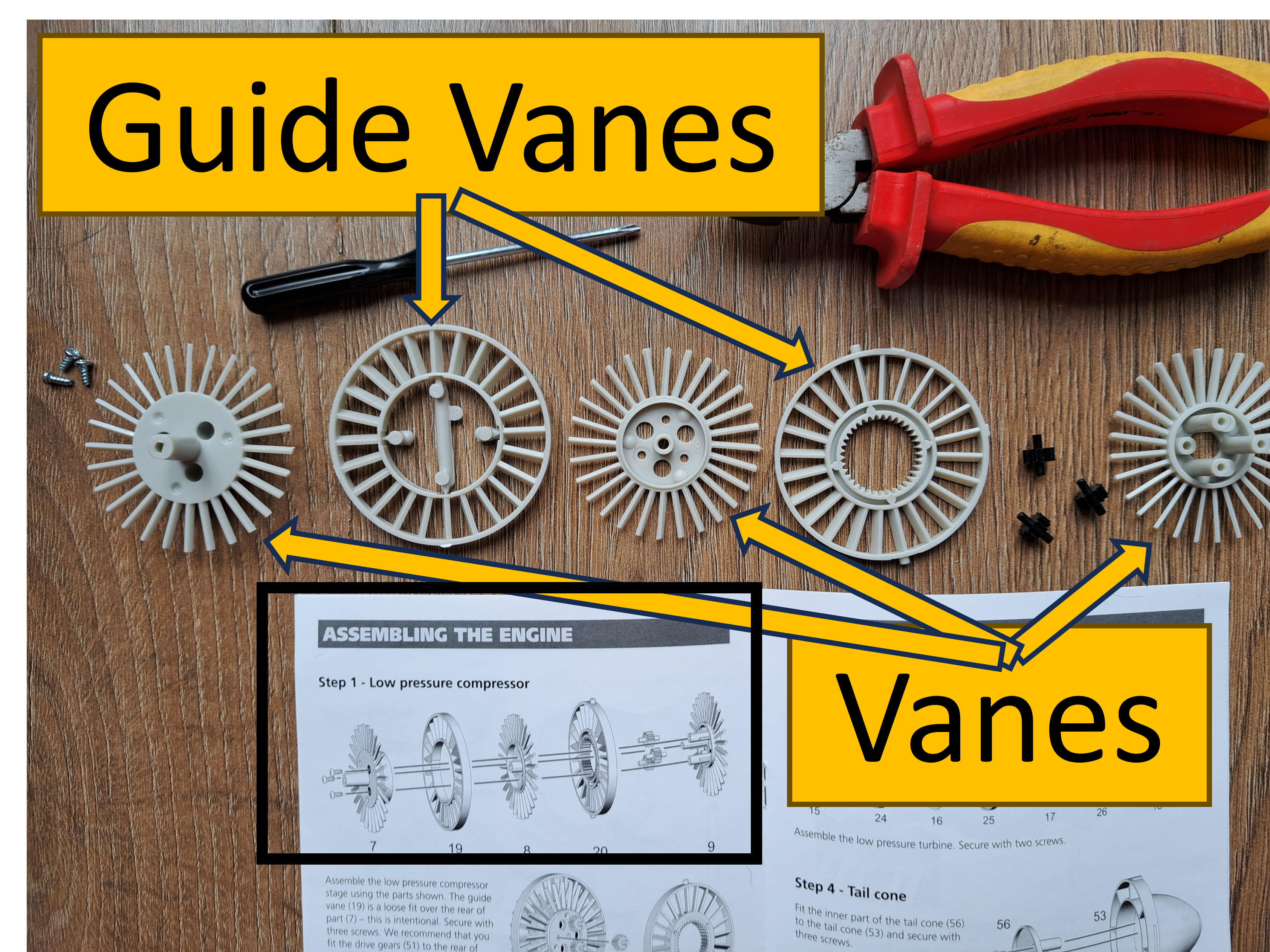
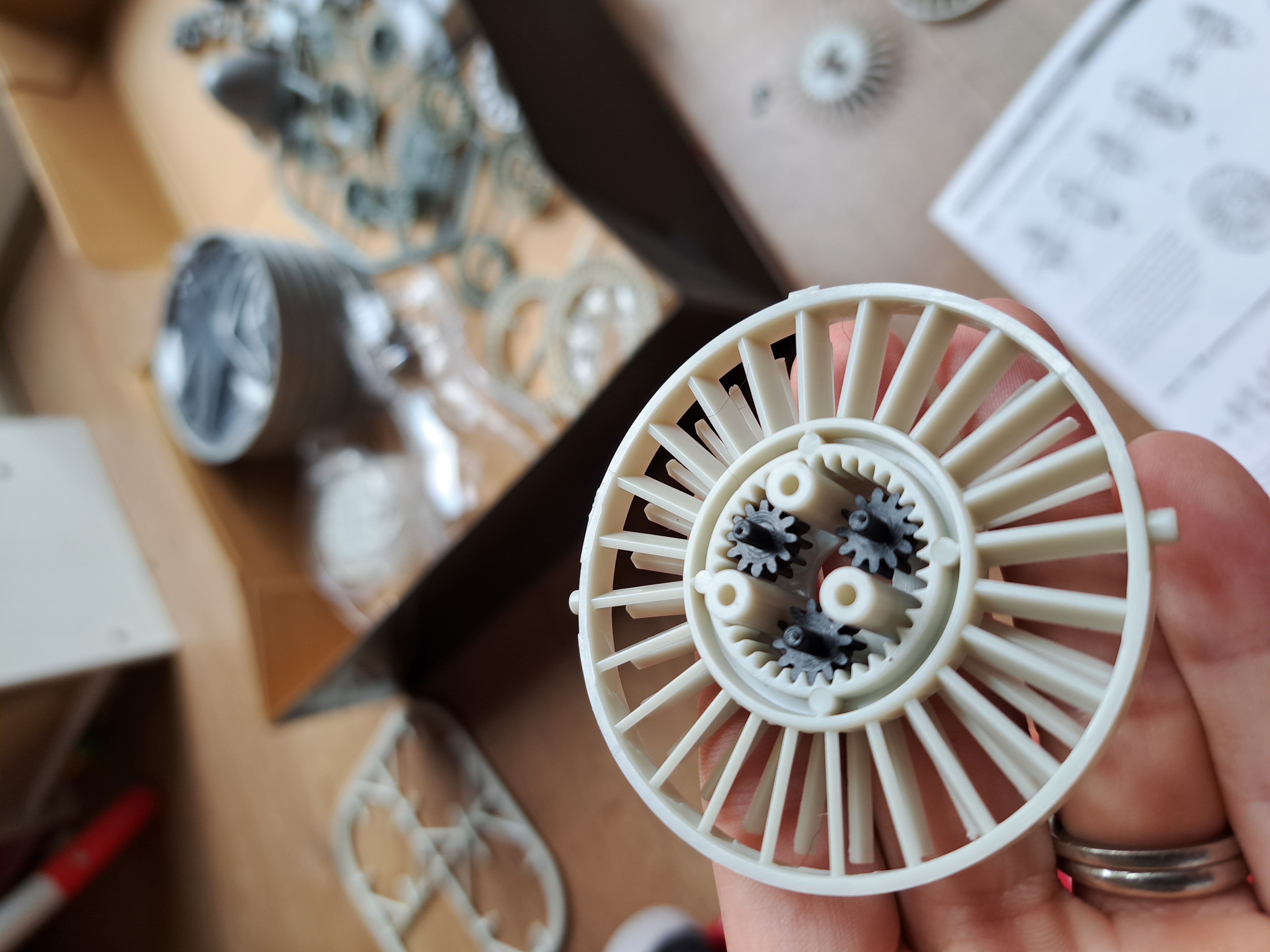
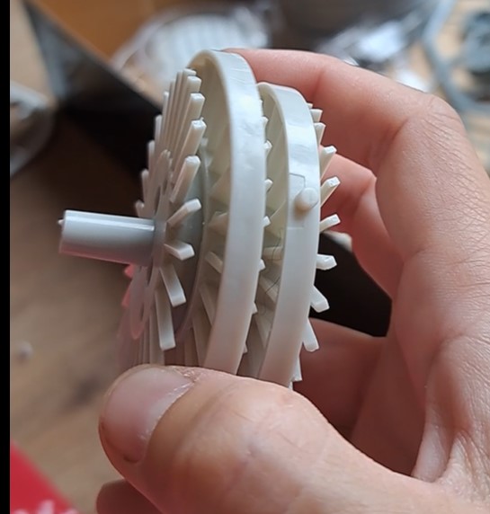
The completed Low Pressure Compressor assembly is shown below. Make sure to clip off/sand down any leftover extra pieces from the plastic frames. I did not do this at first - the final assembly would not move - and I had to disassemble the entire engine to sand the edges.
Step 2: Building High Pressure Compressor and Turbine
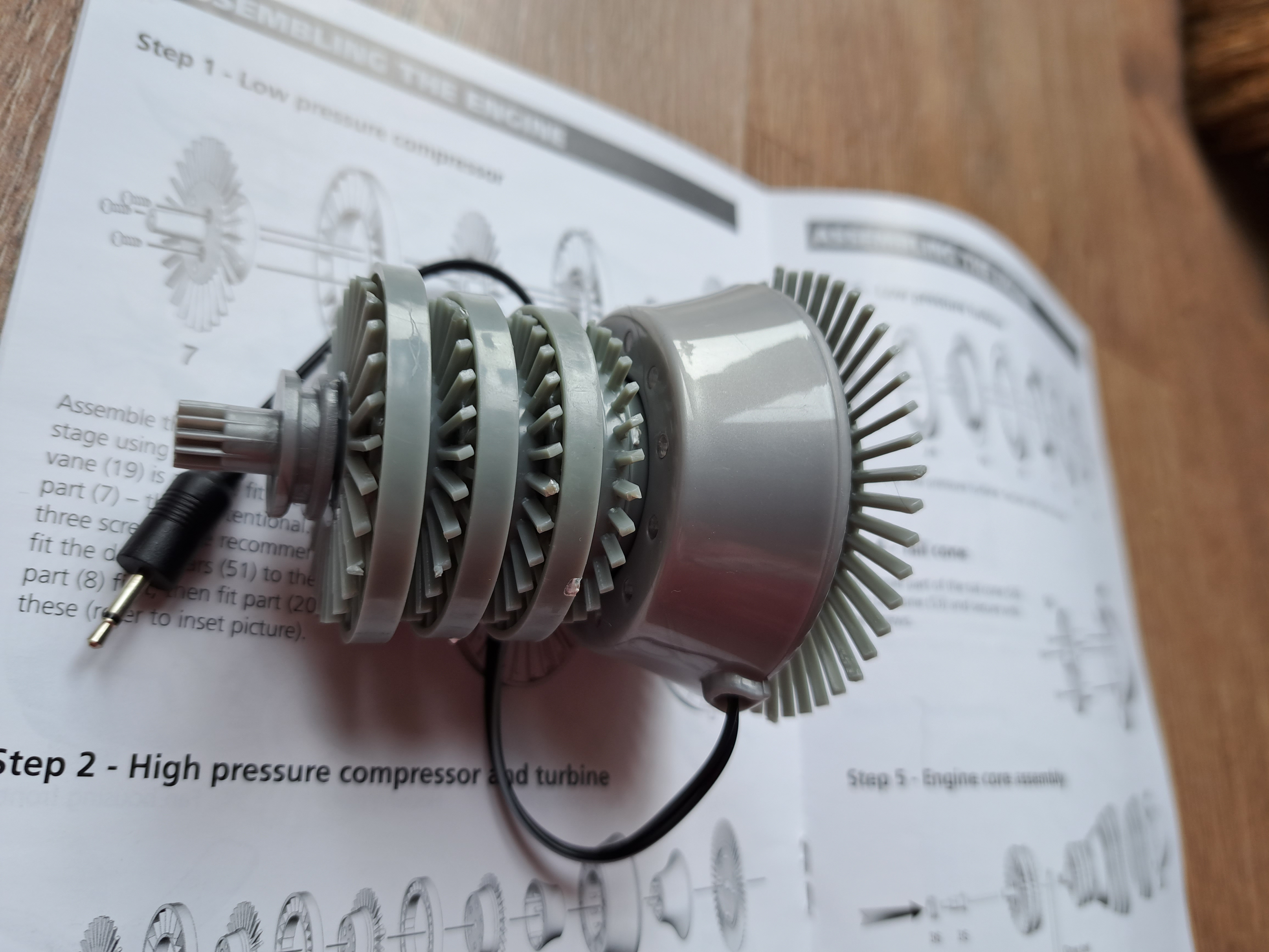
The High Pressure Compressor and Turbine are also made up of alternating compressor vanes and compressor guide vanes - as well as a combustion chamber. The combustion chamber in this kit has red LED lights to represent the combustion location in a real jet engine. The different pieces of the High Pressure Compressor and Turbine are pressed together, rather than using screws. I suggest pressing the pieces together in the middle, rather than pushing on the spokes. I did not have any spokes break in the kit, but I can imagine the spokes can easily break!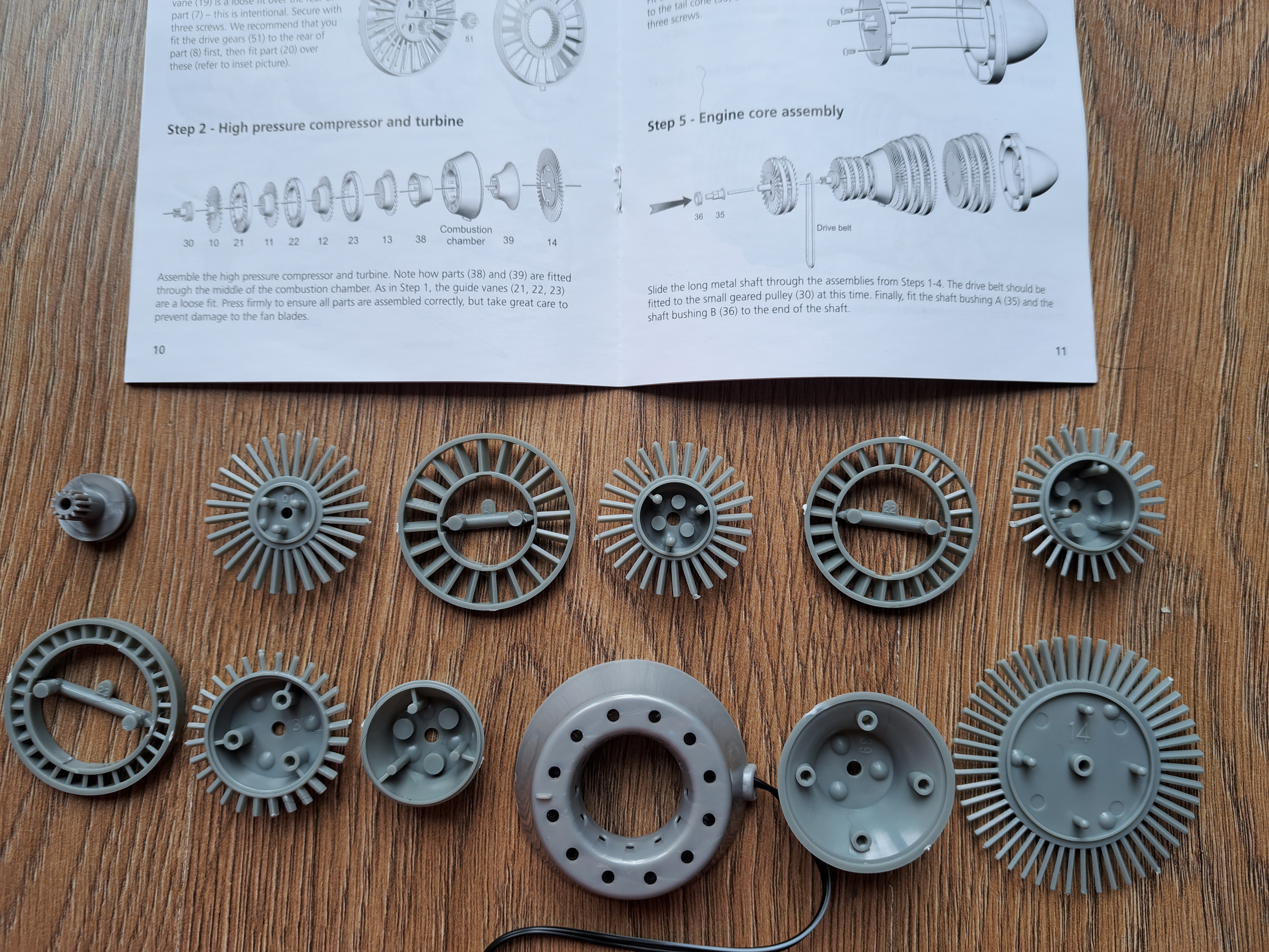
The completed High Pressure Compressor and Turbine assembly is shown below. Again, make sure to remove any leftover pieces from the plastic frames.
Step 3: Building Low Pressure Turbine
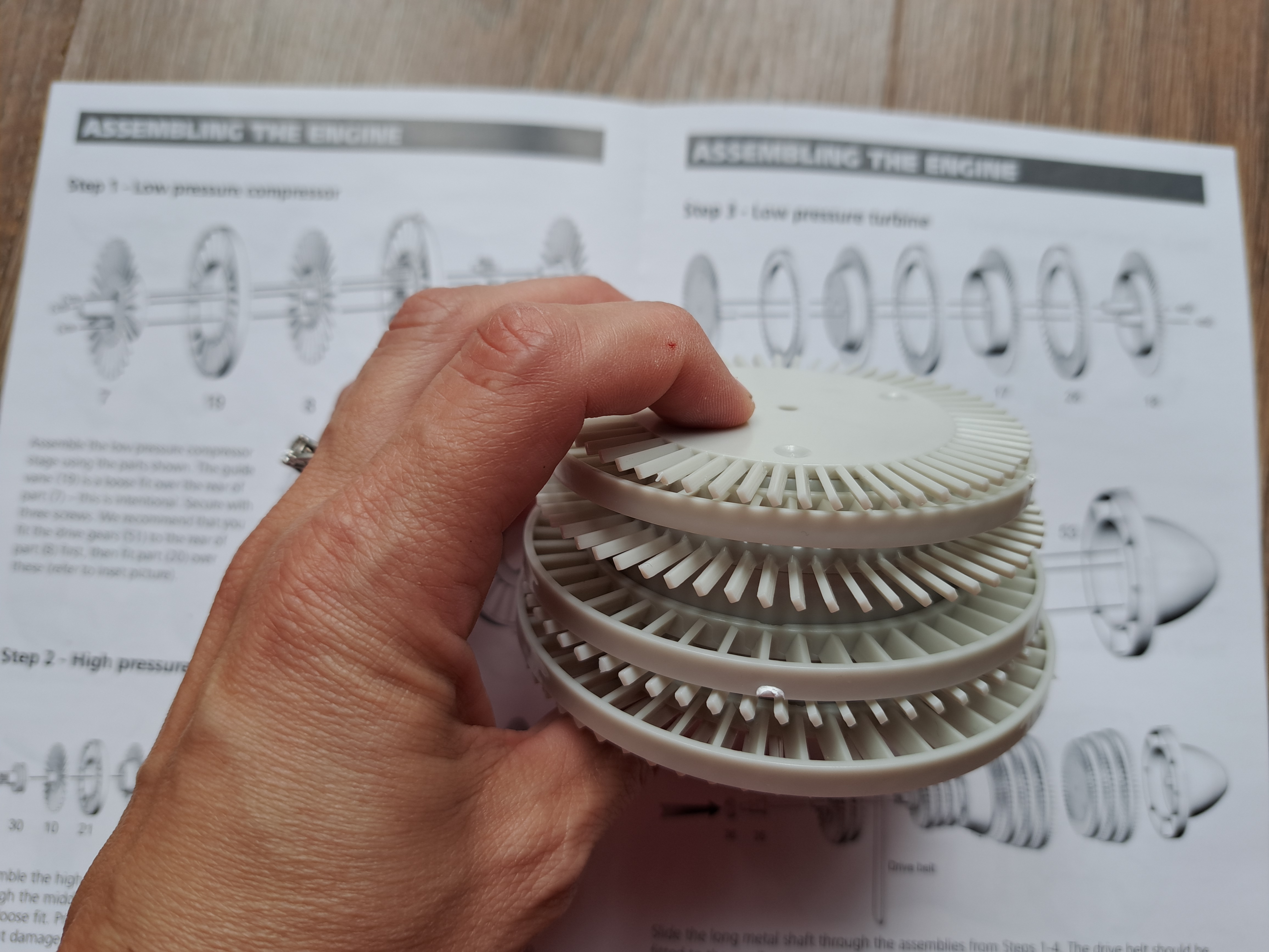
The Low Pressure Turbine is made up of alternating turbine vanes and turbine guide vanes. The pieces are held together with two screws. Again, make sure to remove extra plastic pieces, especially on the turbine vanes. The completed Low Pressure Turbine assembly is shown below.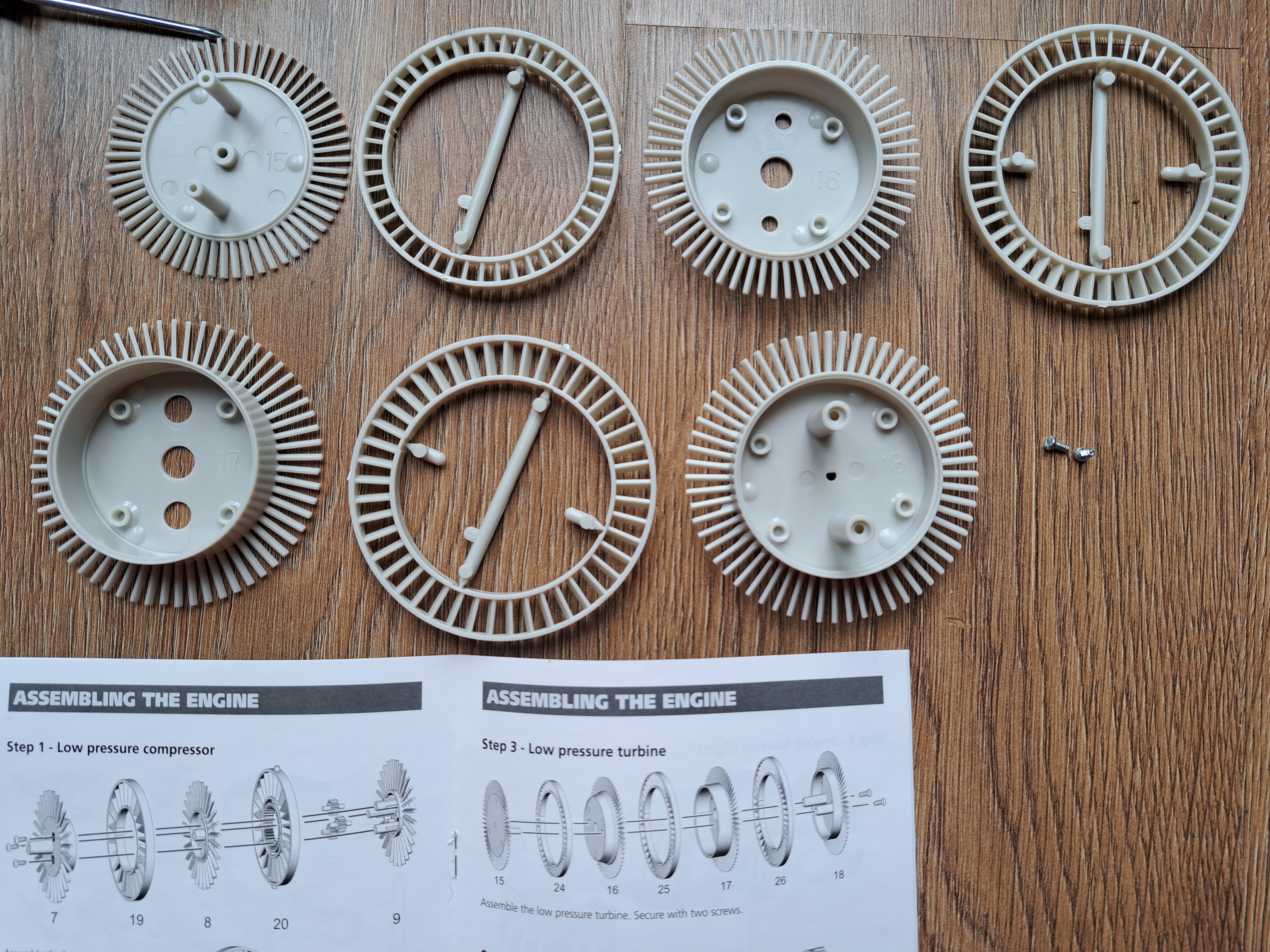
Step 4: Building Tail Cone
The tail cone is made up of two pieces which are held together with 3 screws. This could easily have come as a single part but I imagine needed to be separate to make the kit >40 pieces!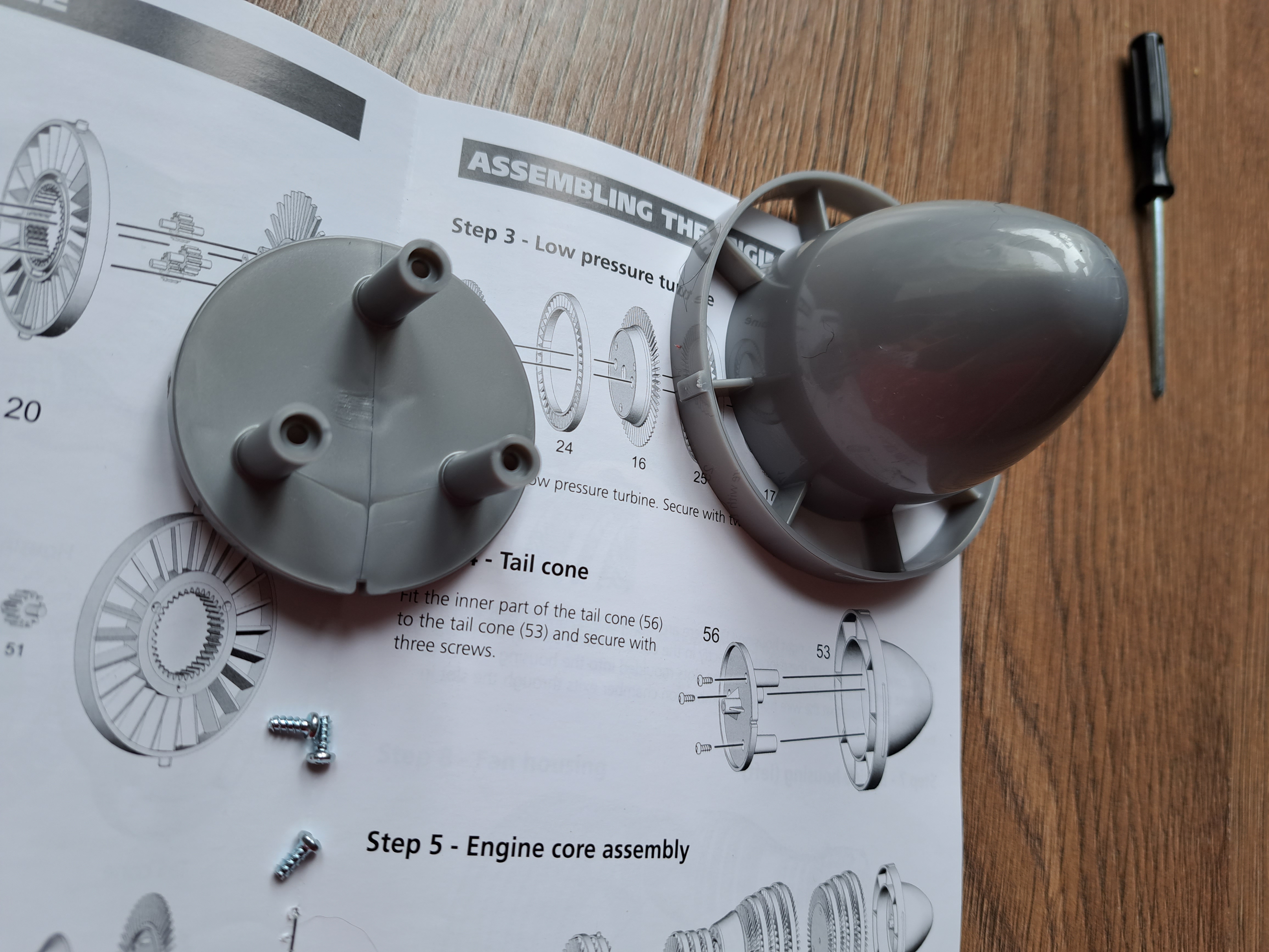
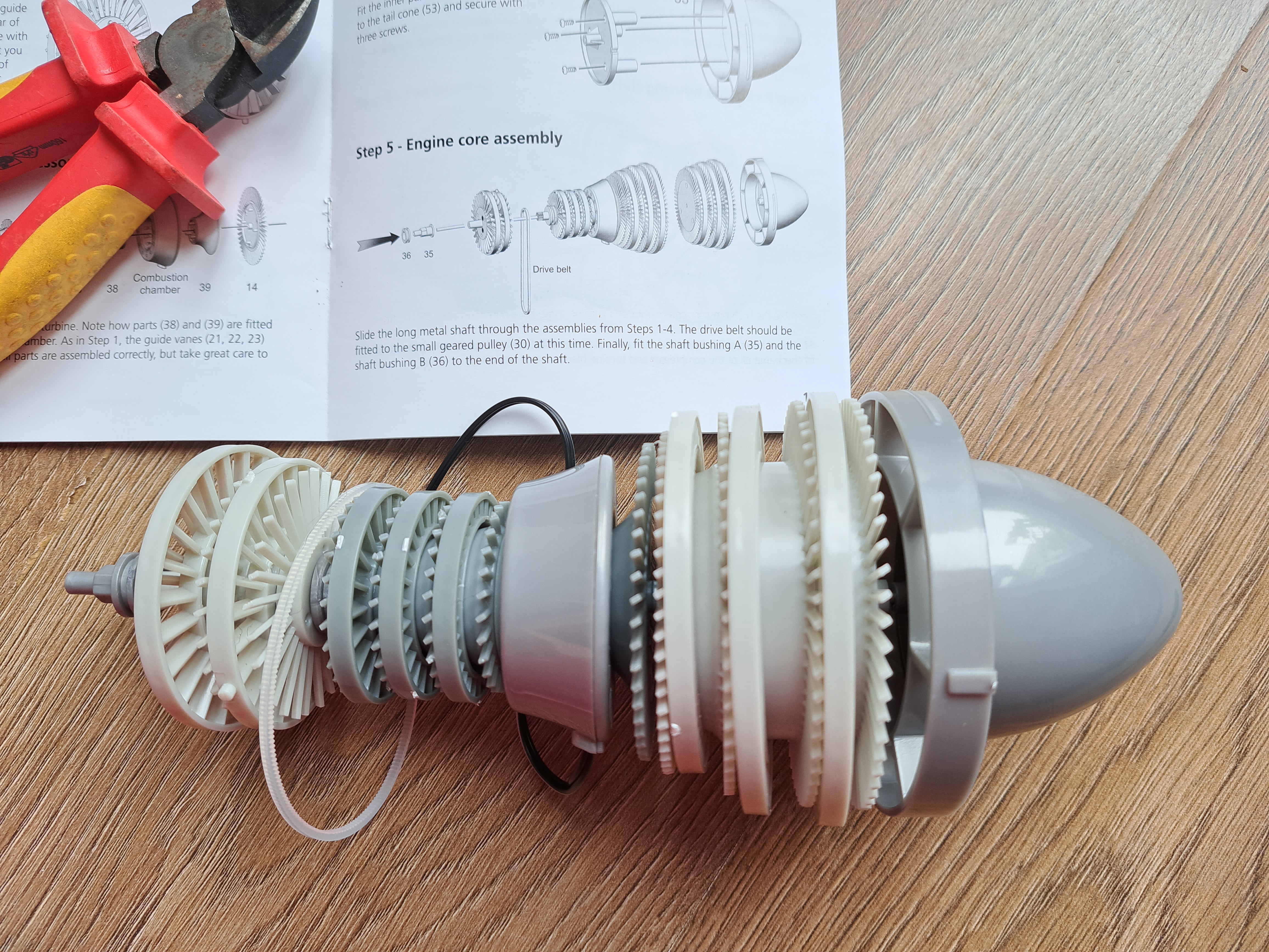
Step 5: Building Engine Core Assembly
In this step, a shaft is put through the centers of the Low Pressure Compressor, High Pressure Compressor and Turbine, Low Pressure Turbine, and Tail Cone. This unit is called the "engine core". The shaft should pass through the entire engine core. If the shaft does not reach both ends of the engine core, check that the parts have been added correctly. I accidentally put the Low Pressure Compressor on backwards the first time. After assembling the engine core, add the drive belt around the small geared pulley in the High Pressure Compressor and Turbine. Note, the belt goes in the smooth groove of the pulley, not around the part's teeth (the teeth should go into the Low Pressure Compressor drive gears).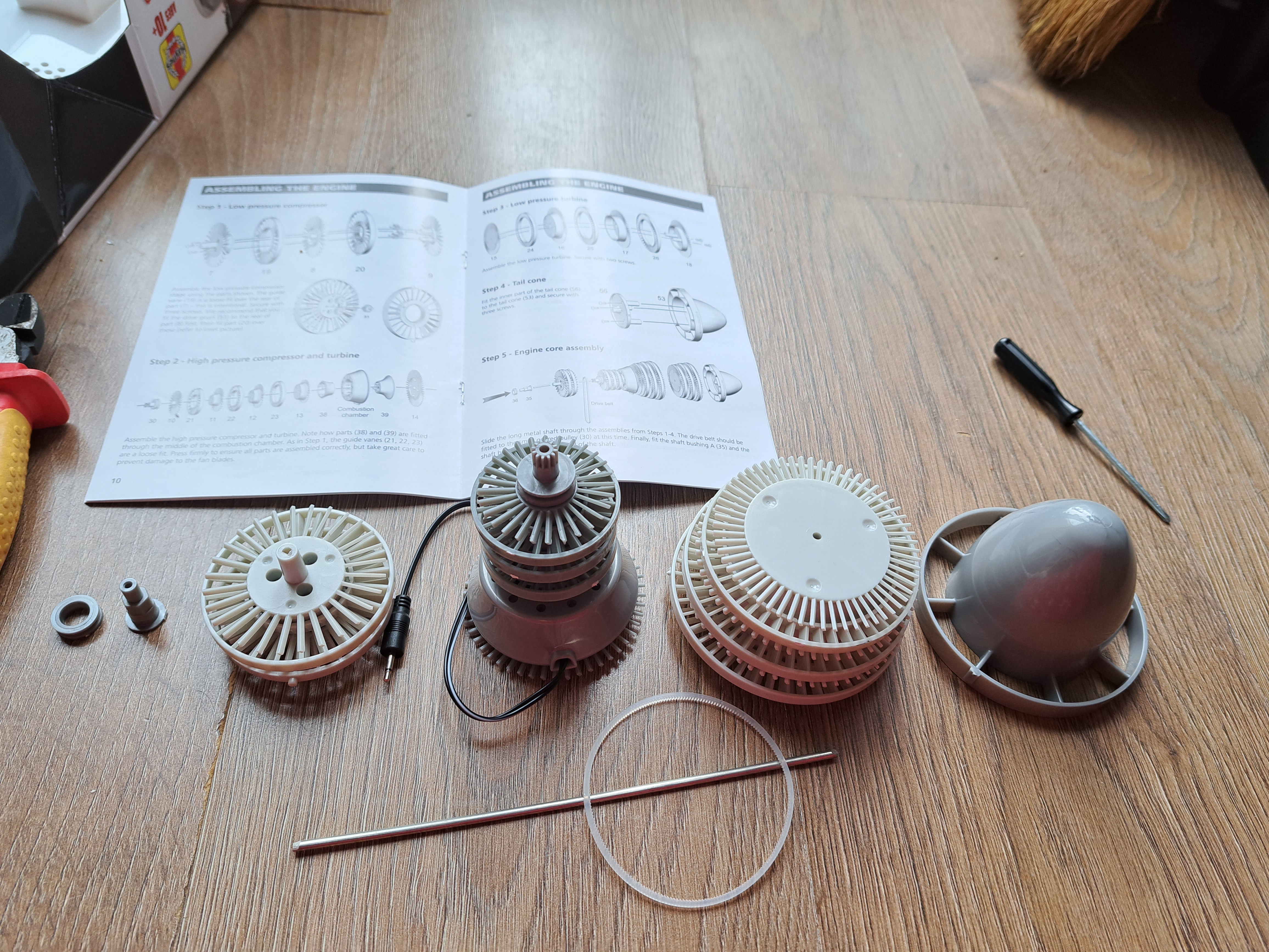
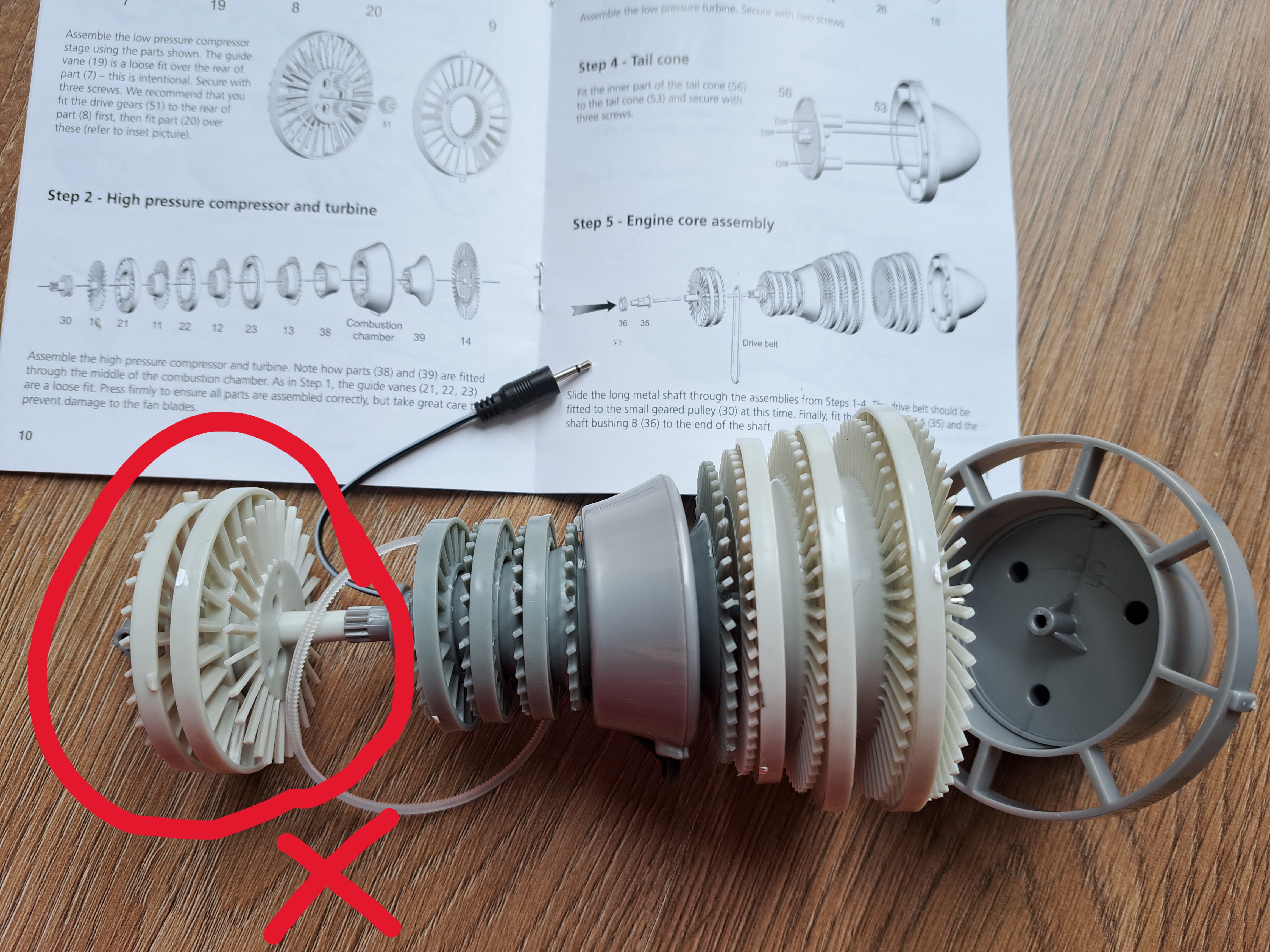
The correctly assembled engine core is shown below.
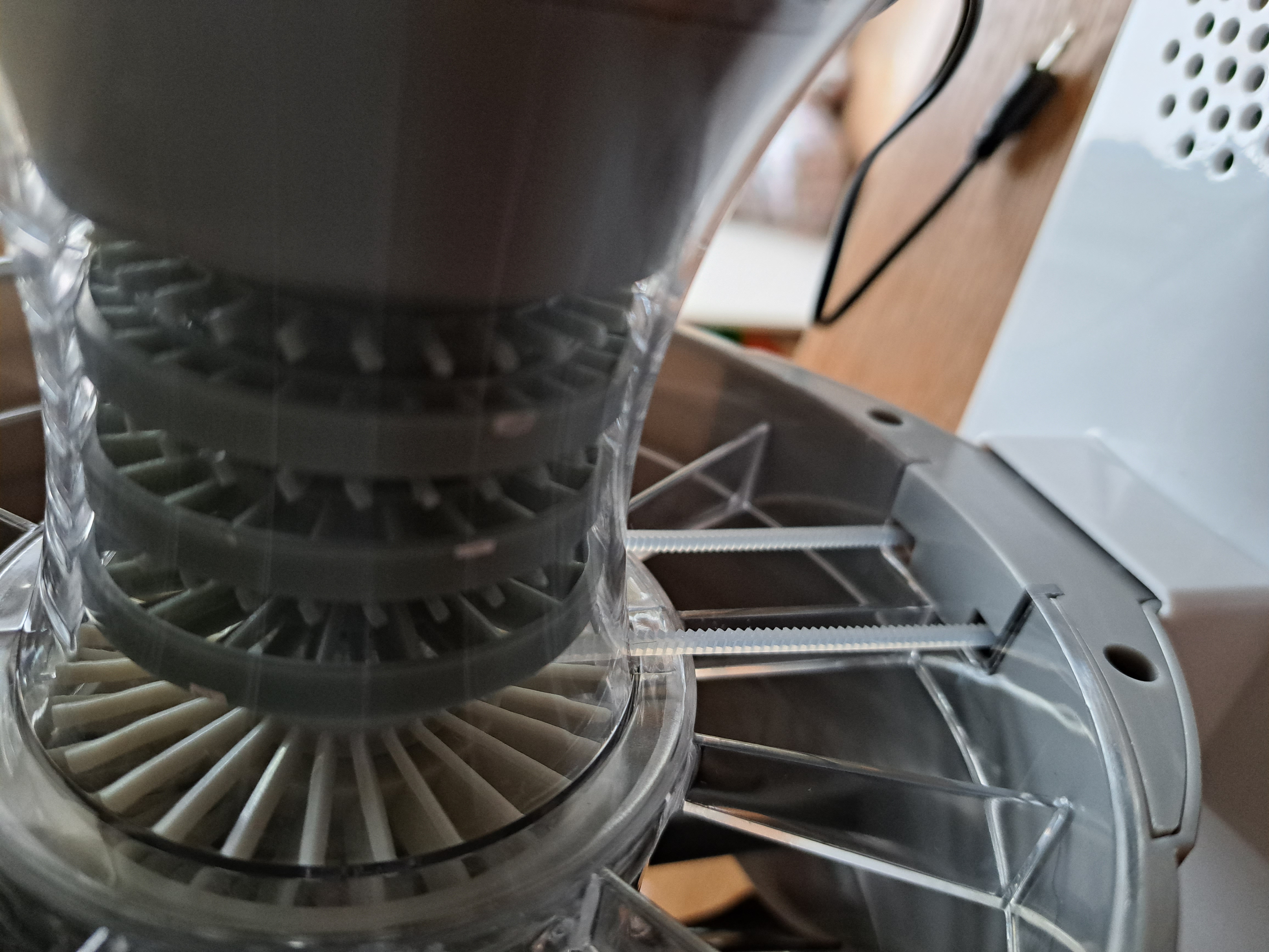
Step 6: Enclosing Engine Core Assembly within Engine Housing
The engine core is then enclosed in clear plastic housing. The housing has slots that the guide vanes fit into. I found it easiest to fit the Combustion Chamber first and then fit each guide vane, starting with the ones closest to the Combustion Chamber and then moving away. There are four features that need to be in specific places for the housing pieces to fit together. These four features are marked on the picture below.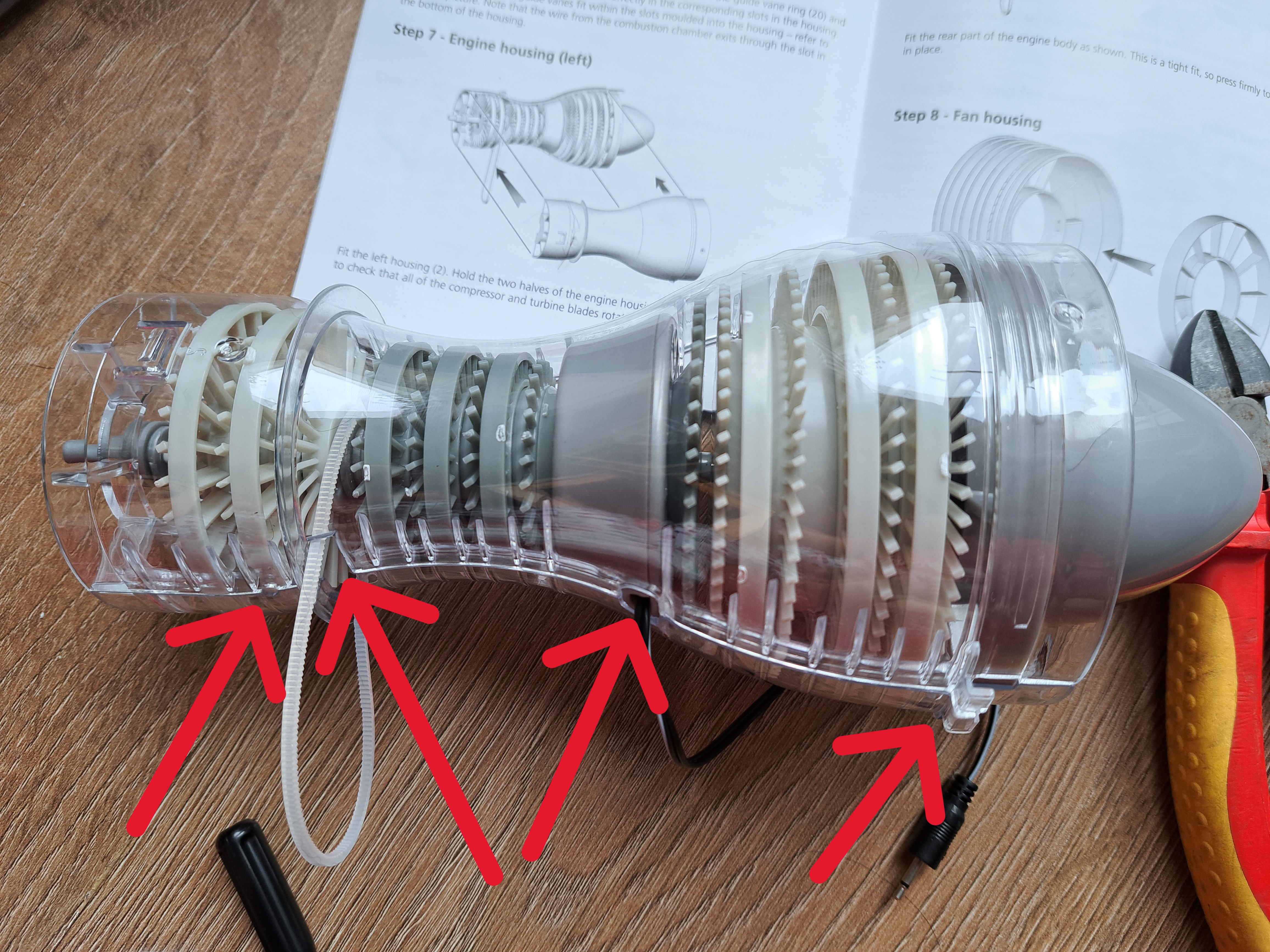
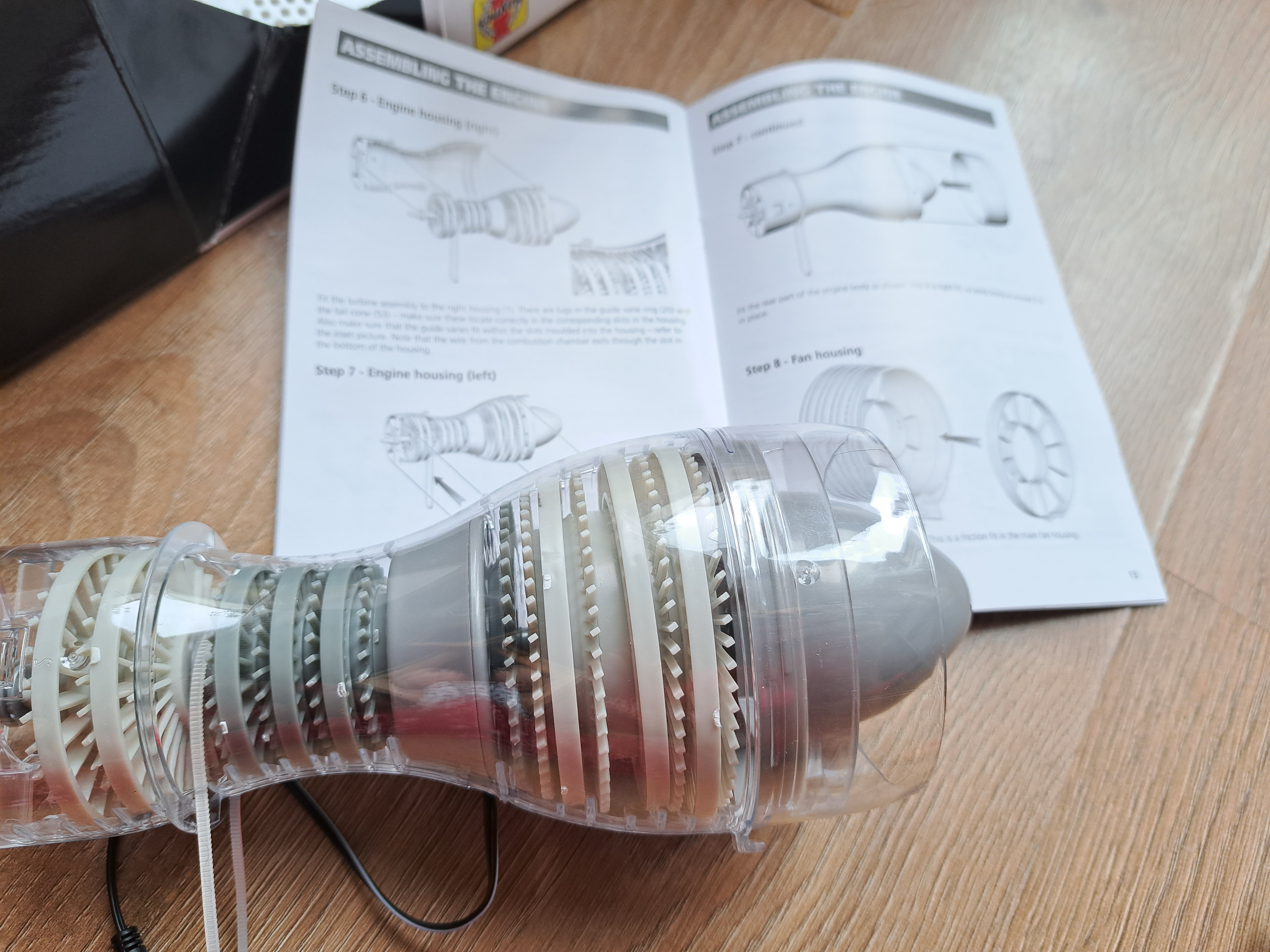
Check that pulling on the drive belt causes the turbines to move as expected. If the turbines don't rotate, take the housing apart and cut/sand any extra pieces of plastic which might be stopping the rotation. If the turbines move freely, add the clear rear housing. It is difficult but possible to undo this step if you later find the turbines don't turn smoothly. The assembly within the housing is shown below.
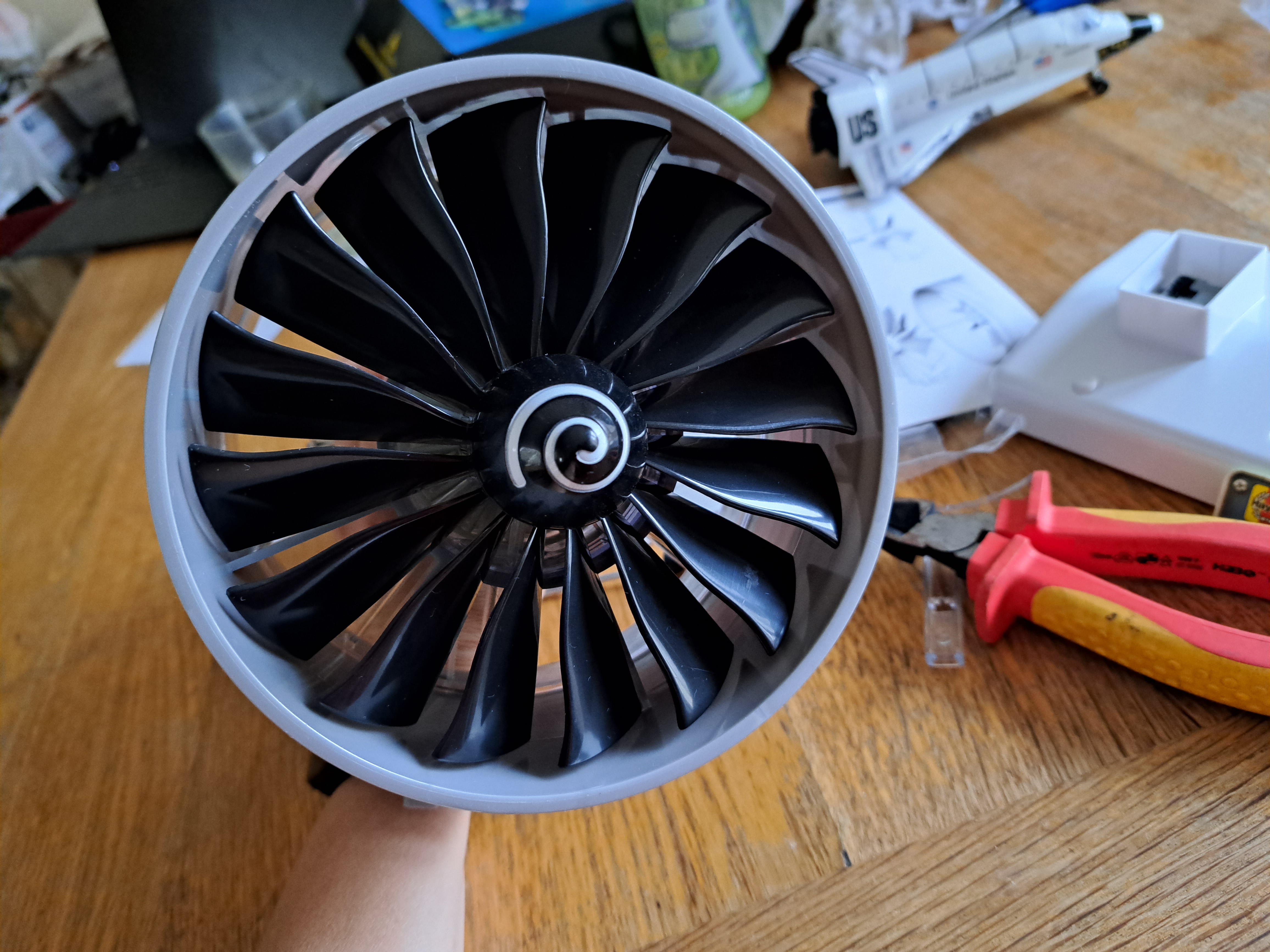
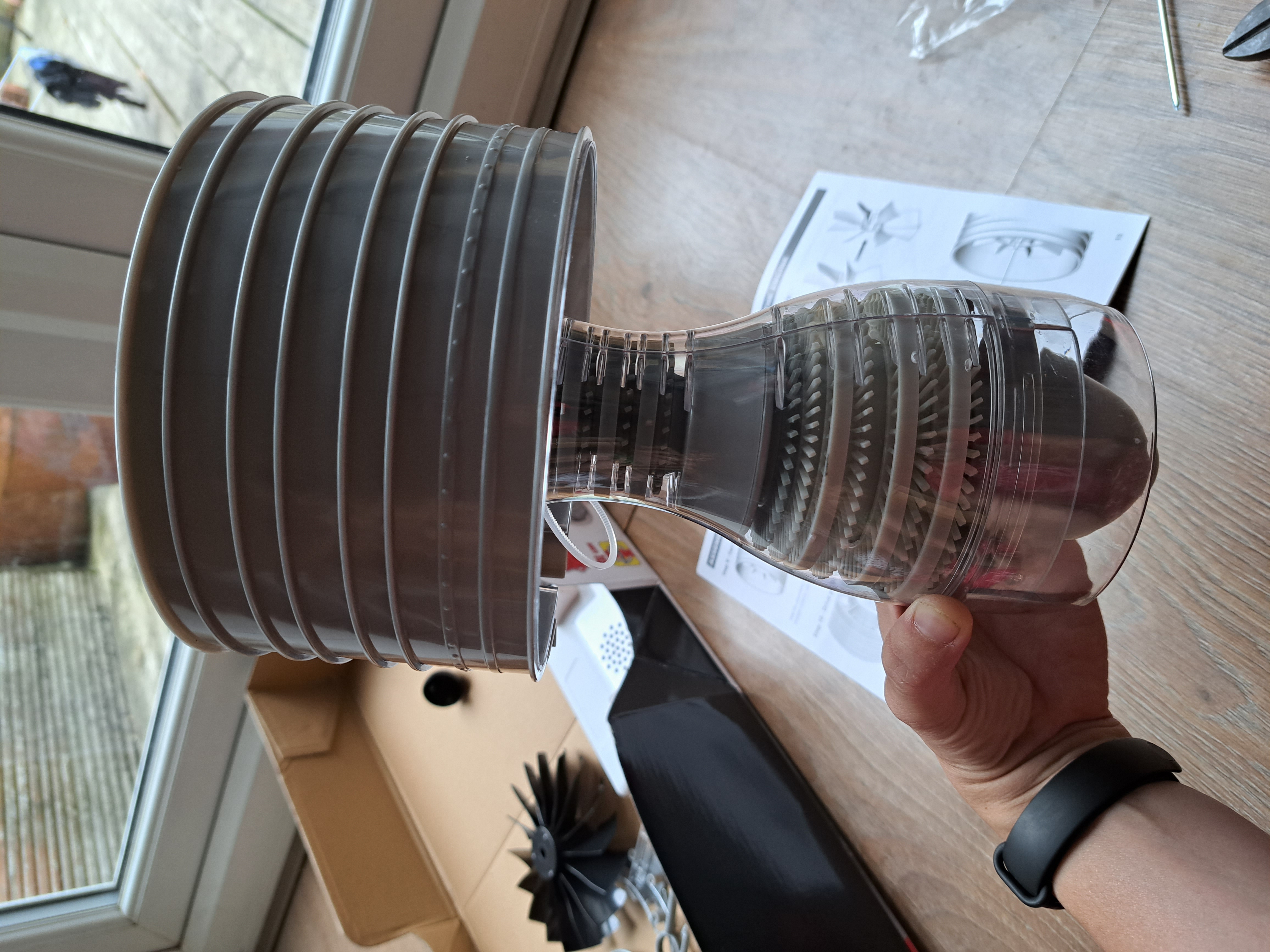
Step 7: Adding Fan Housing and Fan to Engine Core Assembly
The fan housing has two rows of guide vanes and a central hole, which the engine core slides into. Two pieces slide together to create the fan blades, which are added onto the front end of the engine core in the fan housing. A swirl nose piece is fitted onto the center of the fan blades. These steps are also difficult (especially removing the swirl piece!) but possible to undo if necessary. At this point, the jet engine looks oddly like a lamp!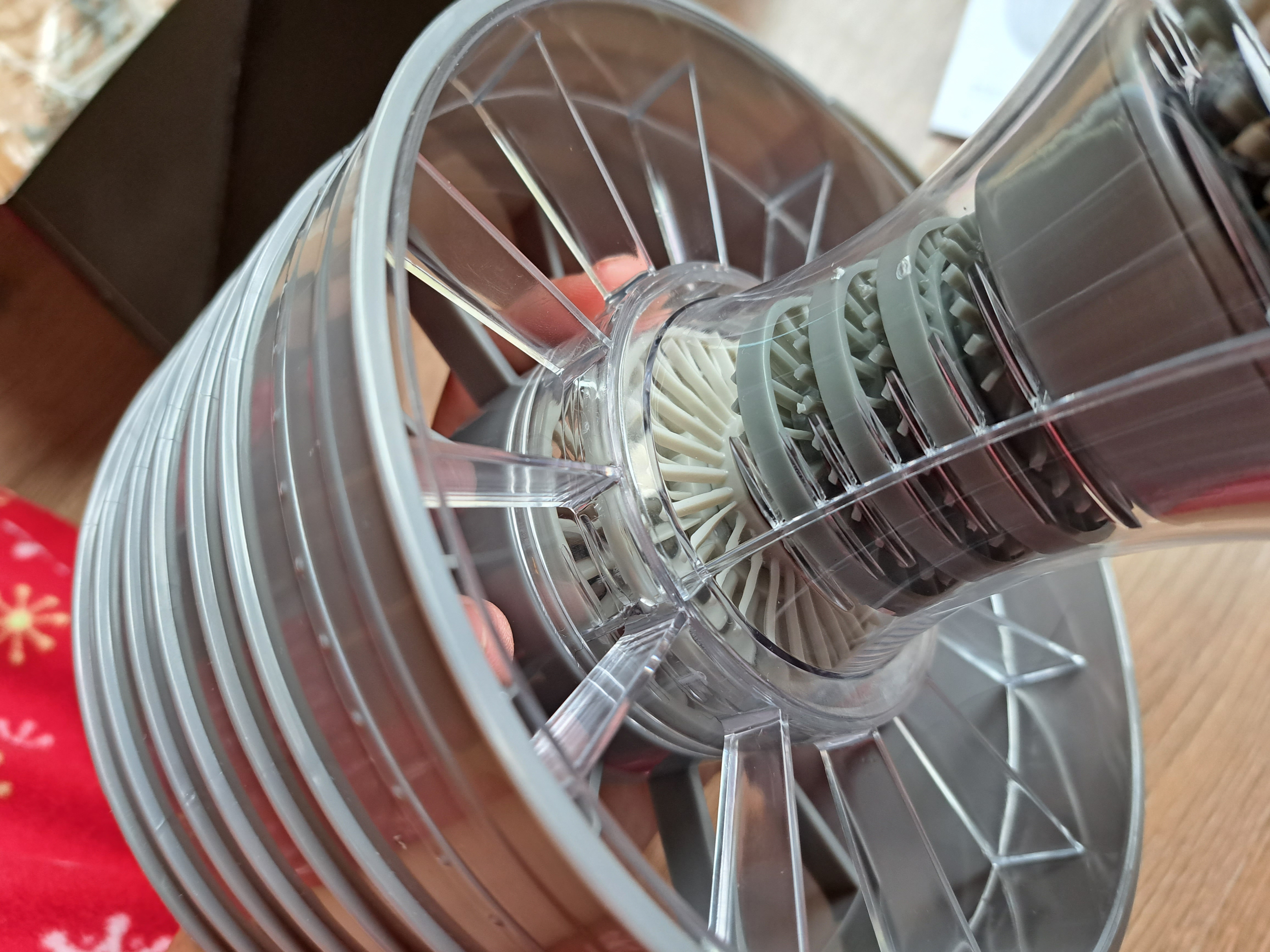
Step 8: Preparing Drive Pulley
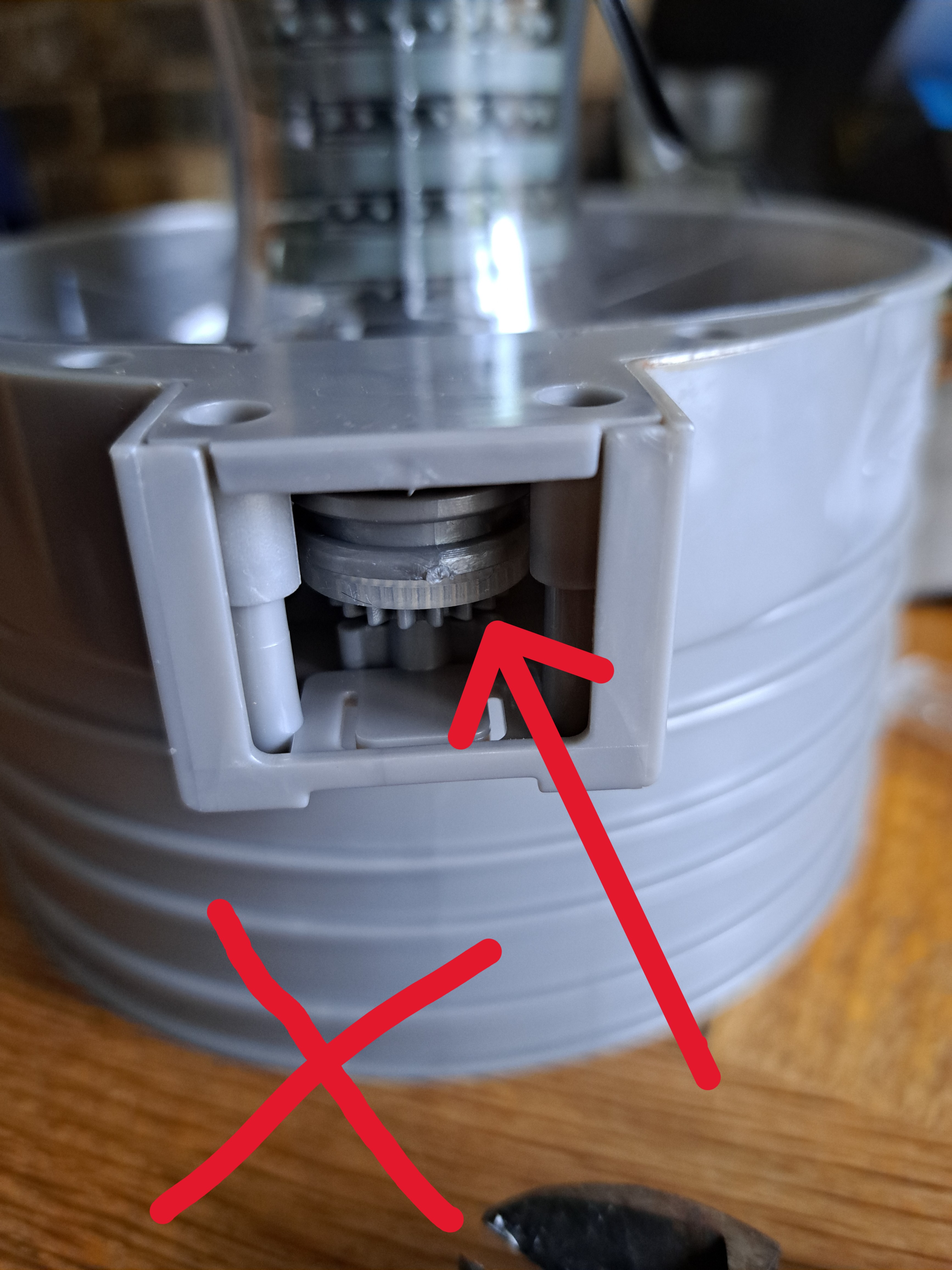
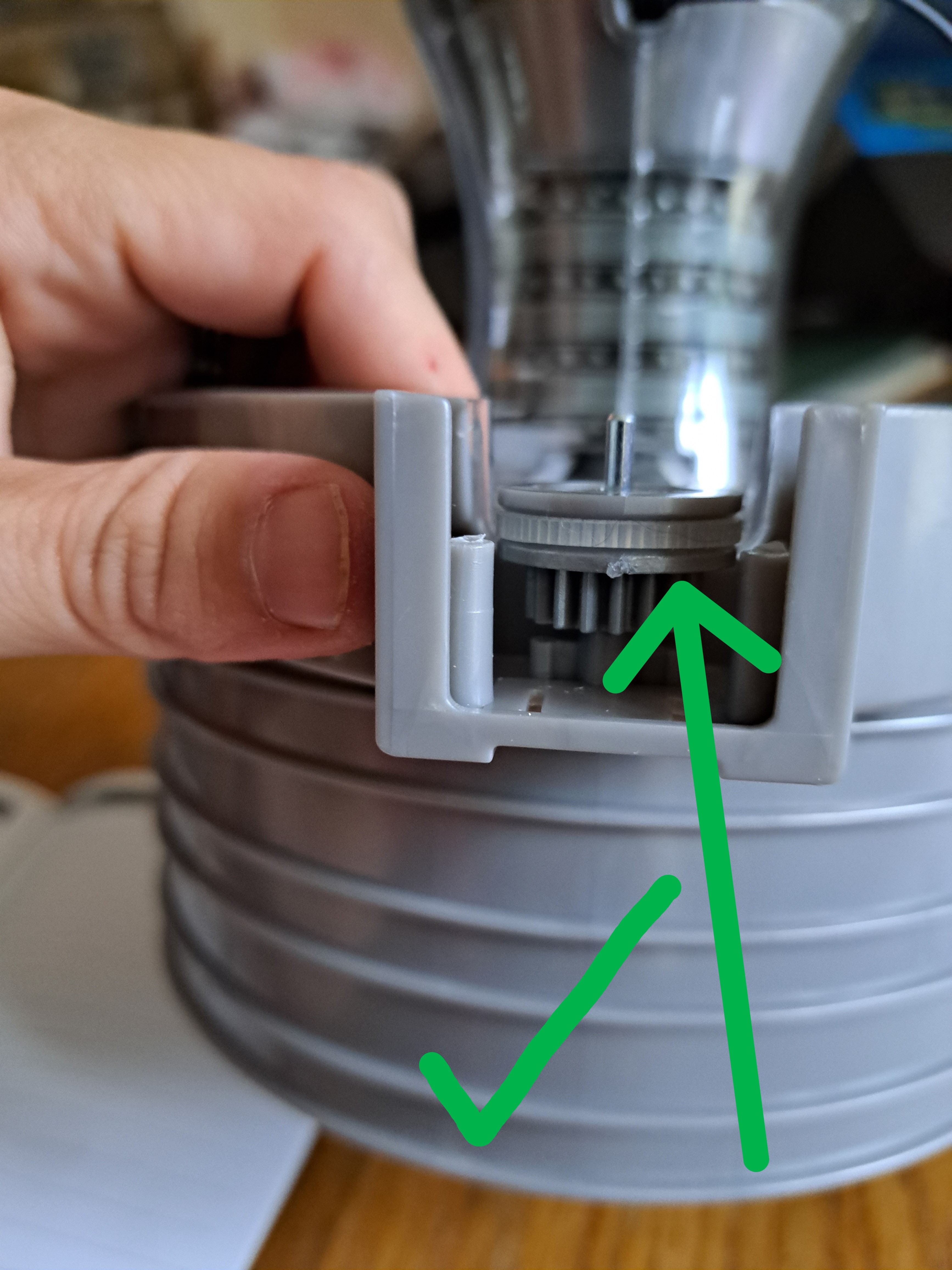
The drive pulley runs from the smooth groove of the small geared pulley in the High Pressure Compressor and Turbine - to the smooth groove of the large geared pulley in the bottom base of the fan housing. Then use four screws to secure the pulley plate.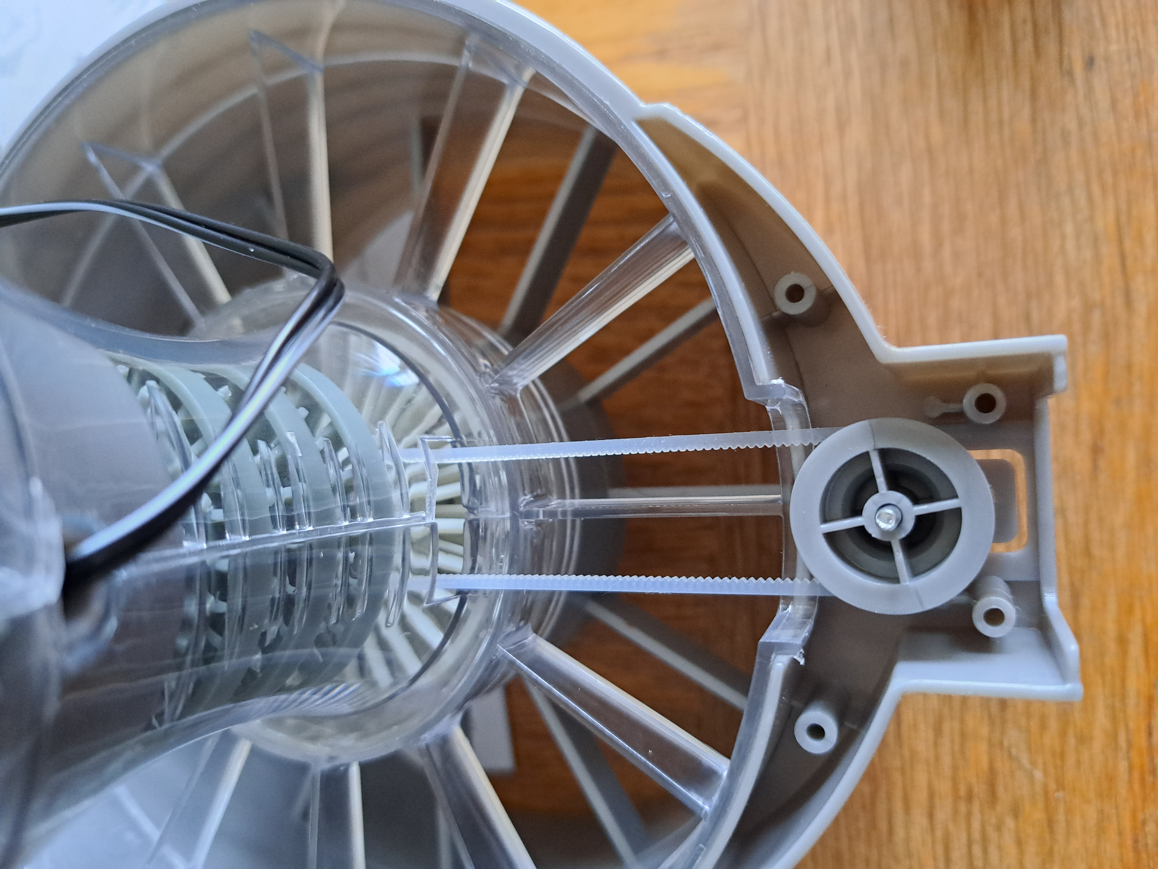
Be sure to put the drive belt into the *smooth* groove and not onto the geared teeth! Gently pull on the drive belt to ensure the turbines still turn smoothly. If the turbines don't move smoothly, check that the drive belt is on the smooth grooves of both pulleys.
Step 9: Mounting and Using the Jet Engine
The jet engine is now ready to mount onto the base. The bottom of the fan housing clips into the larger slot on the base. The engine core sits on top of a holder which inserts onto the base. Add 3 AA batteries to the base. Plug in the Combustion Chamber, and press the button on the base to make the jet engine begin. It will run - *VERY LOUDLY* for approximately 30 seconds. Cover the speaker with your hand if you want the sound quieter! I suggest re-reading the explanation booklet with the jet engine running in front of you now.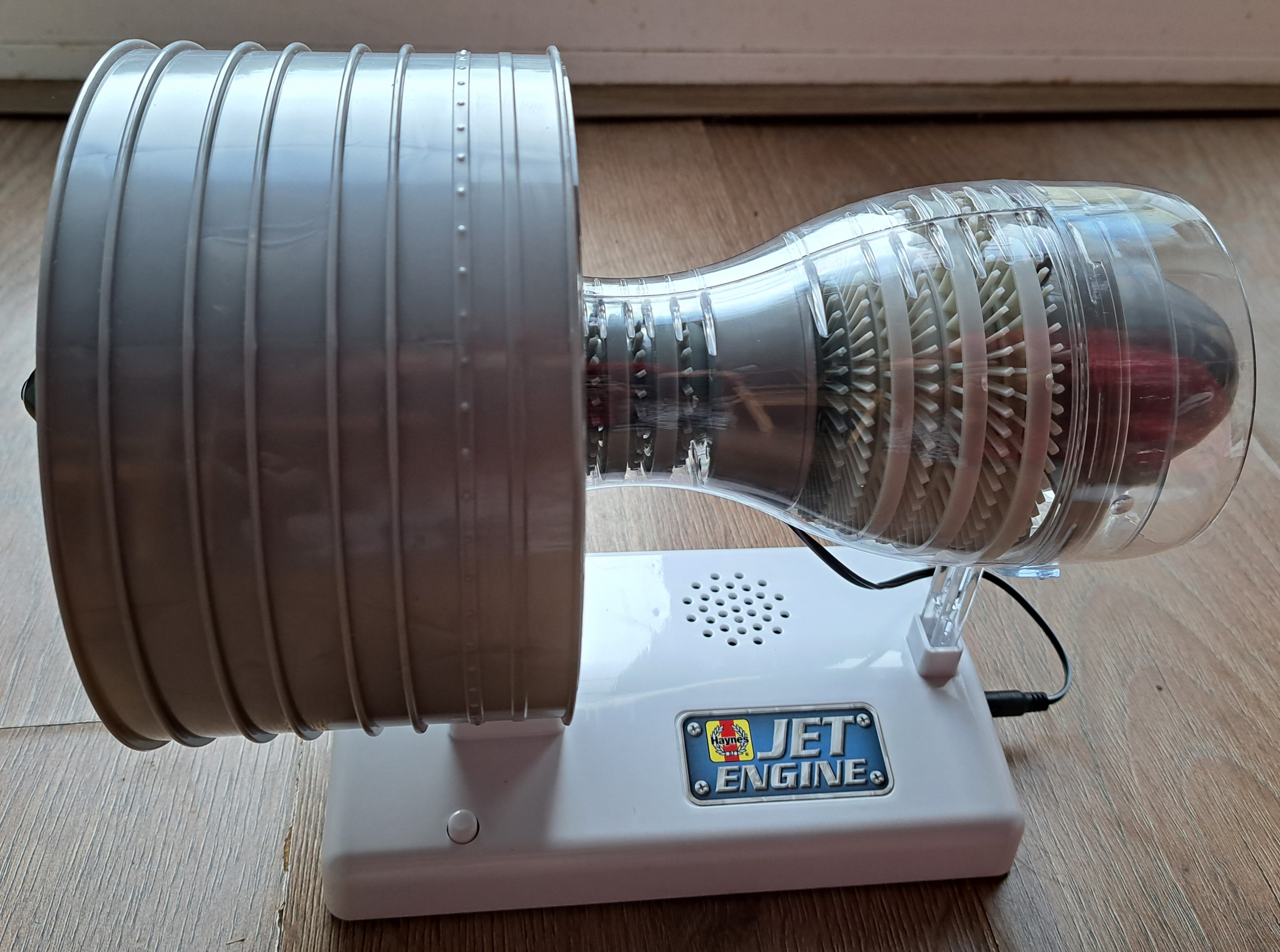
A Final Overview!
Things I really liked:-Assembly instructions are very clear.
-Color coding and numbering parts make kit much easier to assemble.
-Explanation of how a jet engine works is useful (although explanation made more sense after building kit).
Things I suggest improving:
-Making jet engine sounds a bit quieter.
-Reducing price point of kit from £40 to ~£25.
-Allowing more tolerance between vanes and engine core housing so that small amounts of extra plastic pieces does not stop the engine.
This kit is a quick build of a simpler machine than Machine Works' Internal Combustion Engine. For this reason, I think this kit would be ideal as a first project for a child interested in becoming a mechanical/aerospace engineer. The assembled kit would also work well as a teaching tool or desk talking item for someone already involved in aerospace engineering.
Other Articles:
Quantum MechanicsA no-nonsense description of quantum mechanics with no maths or philosophy. The concepts are explained with animations, which are mainly computer simulations of electrons. |
|
Benzene QMC GalleryA gallery of images from an attempt to model the benzene ground state using a variational and diffusion monte carlo method. |
|
|
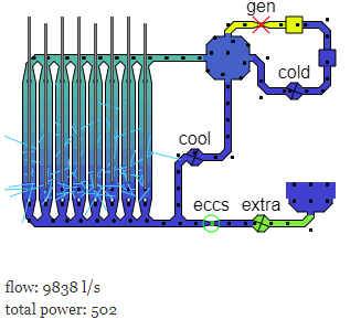
Chernobyl SimulationAn attempt to simulate the normal running, and then accident of the Chernobyl nuclear reactor. |
© Hugo2015. Session @sessionNumber