Review of Keyestudio's Robot Arm KS0488
By Dr Jennifer Martay PE, Course Leader for Medical Engineering at Anglia Ruskin University
I am a Biomedical Engineer, interested in all things engineering and building up my electronics skills. This is the sixth Keyestudio
kit I've put together, following on from a Smart House,
Solar Tracker, and
3 varieties of Robot Cars.
What did I think about this kit?
This kit built a robot arm and joystick controller that were a lot of fun to play with. The robot arm was a great way to
visualize degrees of freedom (DoF), a topic relevant to multiple branches of engineering. I also really liked
using the joystick controller.
This kit required more familiarity with electronics kits and troubleshooting skills than other Keyestudio kits. I needed to
deviate from the instruction manual in multiple places due to parts running out, not being correct lengths to mesh together, or
not being the correct widths to hold screws into slots. I also decided to power the robot arm with 6xAA batteries instead of the suggested
2x18650 batteries.
Individuals interested in mechanisms who are already experienced with electronics kits will enjoy this kit. The kit, in this
format, is too advanced for a first-time builder.
For more details, watch the video below and/or keep reading!
First Impressions
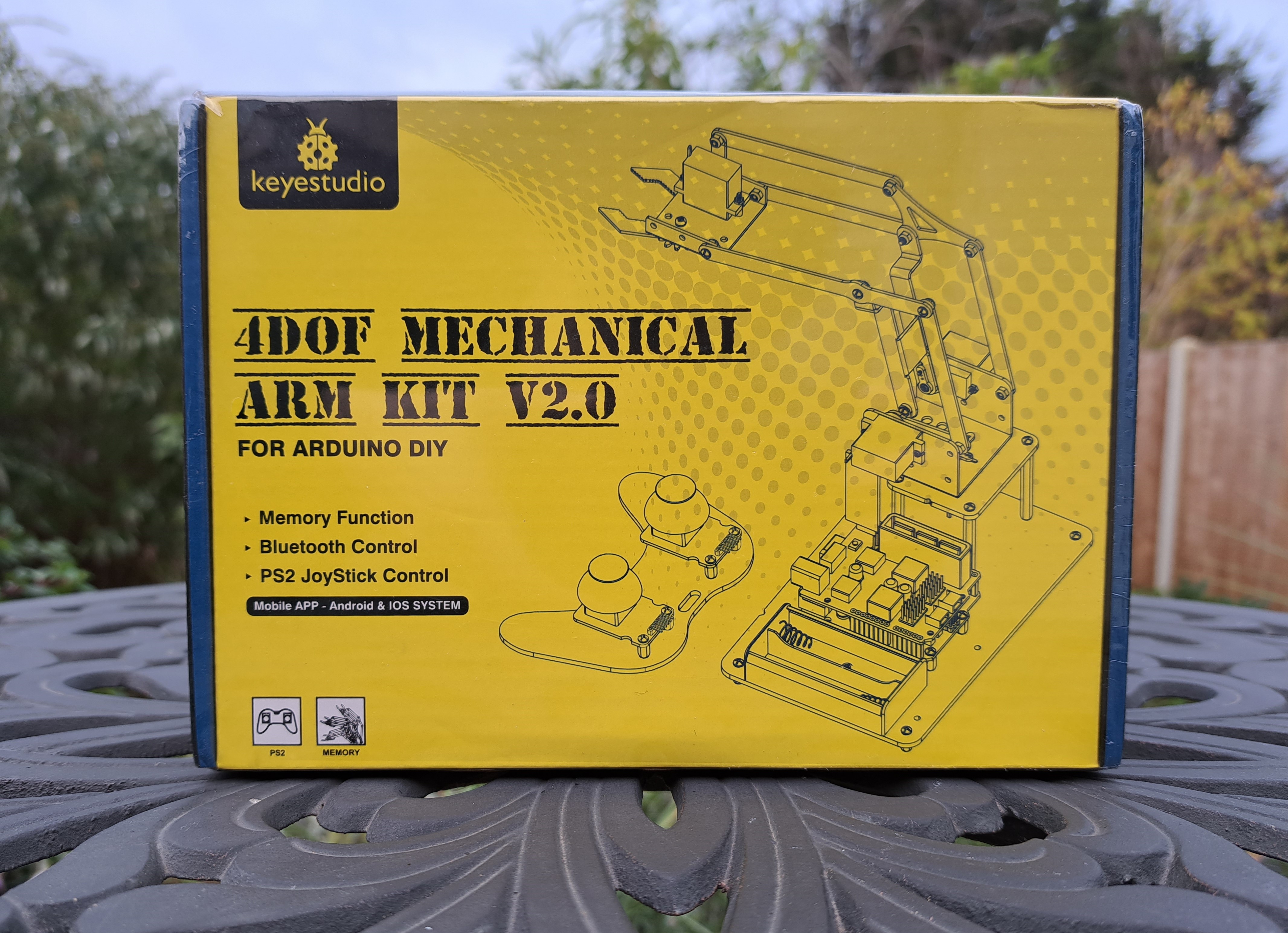
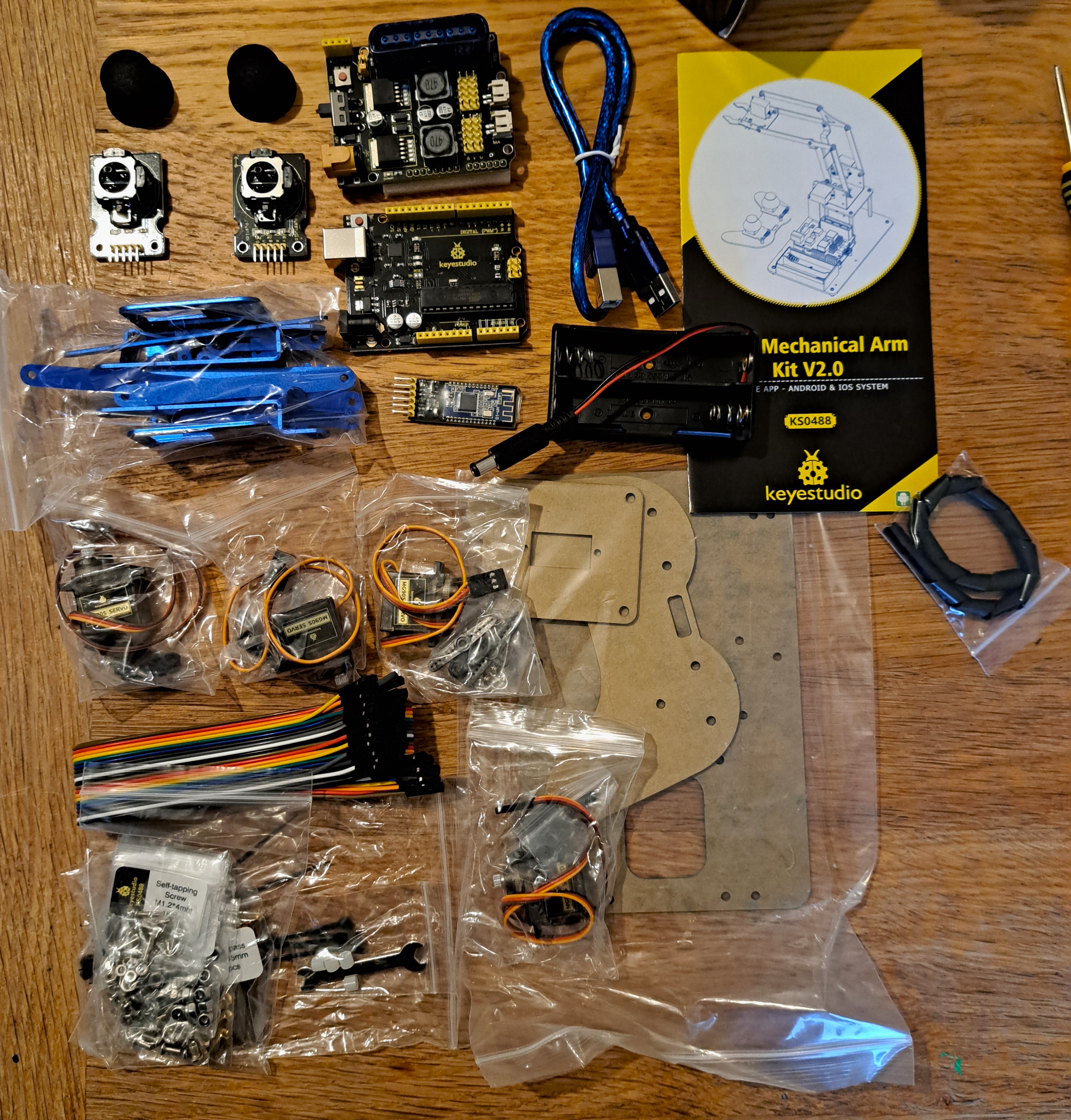
I am really excited to build this kit! We learned about robot arms in my mechanical engineering classes, but this is the first robot arm I've built and operated. The kit comes with 4 metal servos, an Arduino and shield, and a Bluetooth dongle - in addition to pieces to make the robot arm. I especially like the sleek look of all of the blue metal pieces for the crane and claw. I am also looking forward to building my own joystick controller!Links to instructions for building and using the robot arm are also provided.
Assembly Overview
There are 2 pdf's required to build this kit. "Install the claw of the robot arm" is the shorter pdf which explains how to build the movable parts of the robot arm (crane and claw). "KS0488 Keyestudio 4DOF Robot Mechanical Arm Arduino Learning Kit" is the longer pdf that explains everything else: introduction to Arduino and sensors, building the base, mounting the robot arm onto the base, and using the robot arm. It would have been easier for the user if the 2 pdf's were combined into a single pdf. The shorter pdf should begin on page 52 of the main instruction manual.Step 0: Introduction to Arduino, Servos, and Joystick Buttons
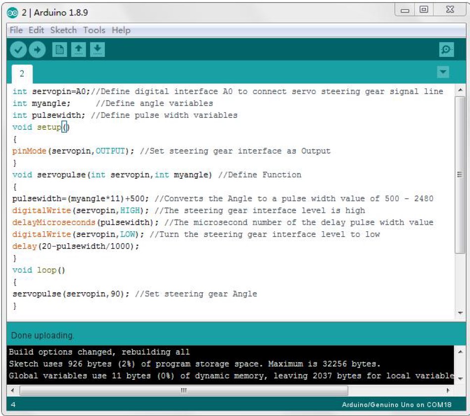
The main instruction manual begins with an Introduction to Arduino. Users are told and shown how to download and use the Arduino IDE. The different components of the Keyestudio uno are shown. Users are then walked through (with pictures and code!) how to connect/use a single servo, multiple servos, and the joystick buttons. These introductions are (see below) extremely useful for Arduino novices - and are easy for experienced users to skip through.Project 3: 1 (p27): 1 servo moves to 0° and then stops. The servo's initial motion is easy to miss (especially if users don't know what to look for/expect!), so novices may think the servo is broken. It might be better to begin with a program where the servo continually sweeps between 0° and 180°. Nevertheless, users need to set the servos to specific angles for the later build so it is very useful to have this code.
Project 3: 2 (p29): 4 servos moving. This program gives inconsistent results when run from a computer without extra voltage/batteries. Some servos don't move at all, while other servos move slowly/intermittantly. The instruction manual warns on p1 that additional voltage is required, but it would be useful to have a reminder on p29 also, especially for novice users. The Test Results on p35 talk about how the 4 servos are moving the robot arm. This is odd as users have not built the robot arm yet so the user is simply looking at 4 servos moving (or not!) on a table. It would be better to place this section after the robot arm is built and wired.
Project 3: 3 (p35): Reading joystick values. This program is easy to do - although, similar to above, would more logically be provided later in the manual after the joysticks are assembled and wired.
Step 1: Build the Base
Each step of building the base is explained and shown. Required parts are listed. Relative positions of parts are shown in figures. The figures also point out important features, such as hole locations, to help users correctly build the assemblies. An example is shown below.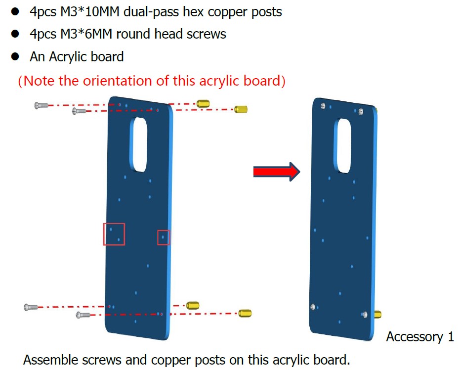
Still, there is room for improvement in the instructions. For example, the battery holder's lead is only long enough to reach the Arduino from one of the two possible positions. The instructions (p42) could indicate which way the battery holder should go. Also, the code provided to set servos' initial position (p47) is unnecessarily complicated.. The code calculates pulse widths and delay, which are not needed. The code on p28-29 is adequate and much simpler.
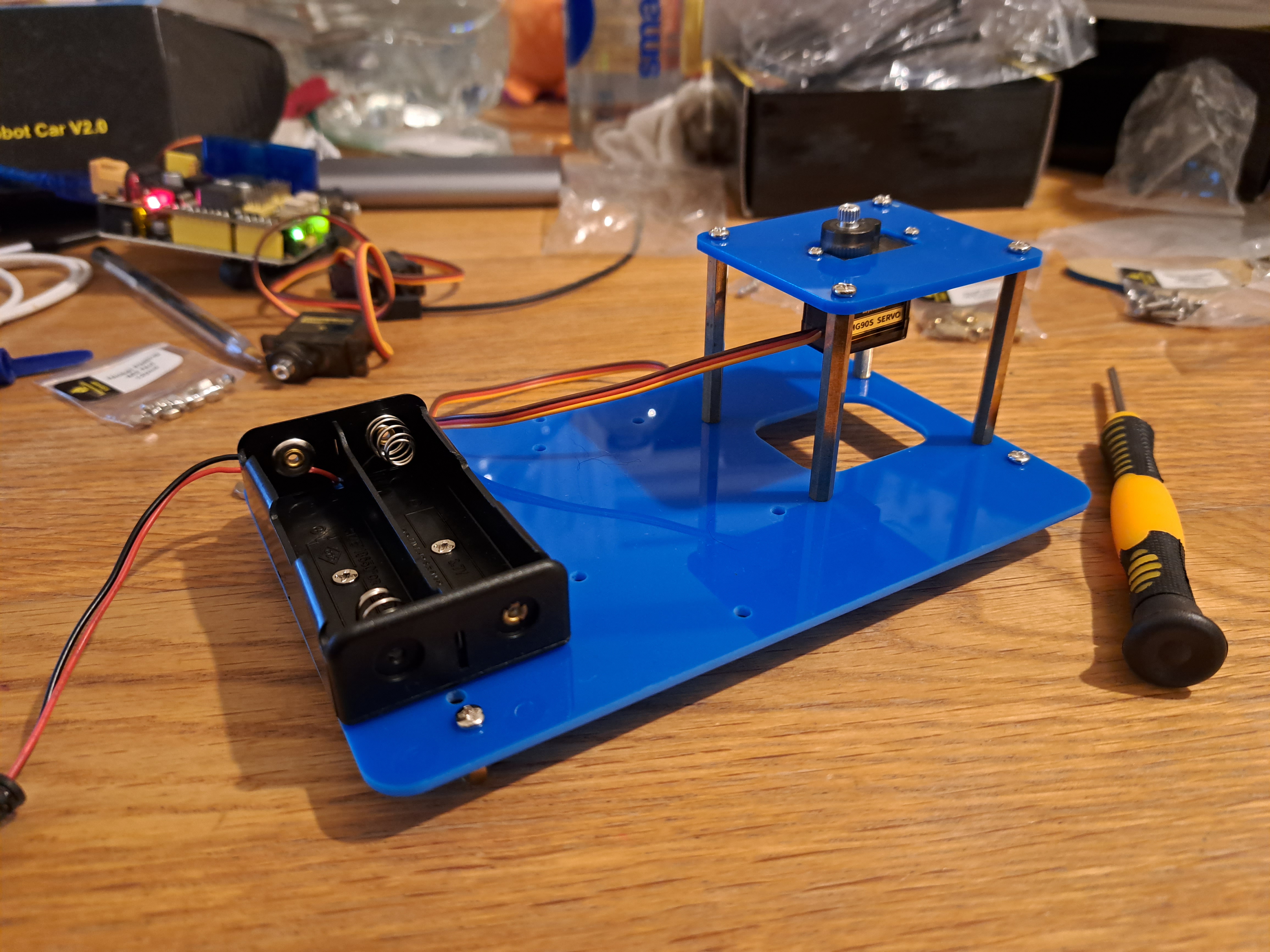
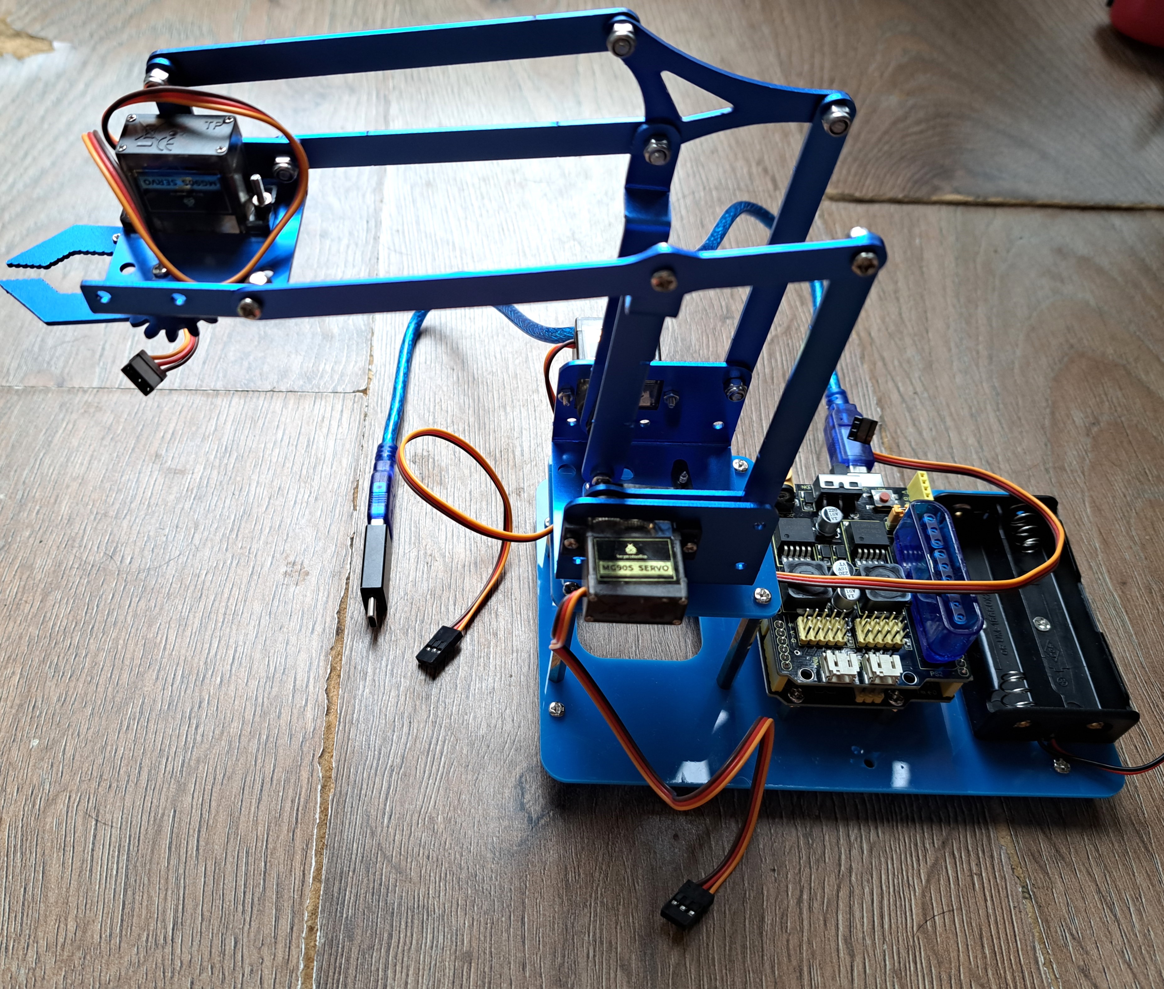
The completed base is shown below (with battery pack in wrong orientation!).
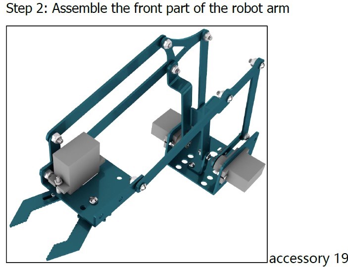
Step 2: Build the Crane and Claw
Deep breath! Here is where the troubleshooting begins!First, the main instructions jump from just the base to assemblying the below contraption onto the base. WHAT! Where did THAT come from?!? Do I have to guess how to make THAT?? No. Calm down. Remember that second pdf I mentioned? Open it....
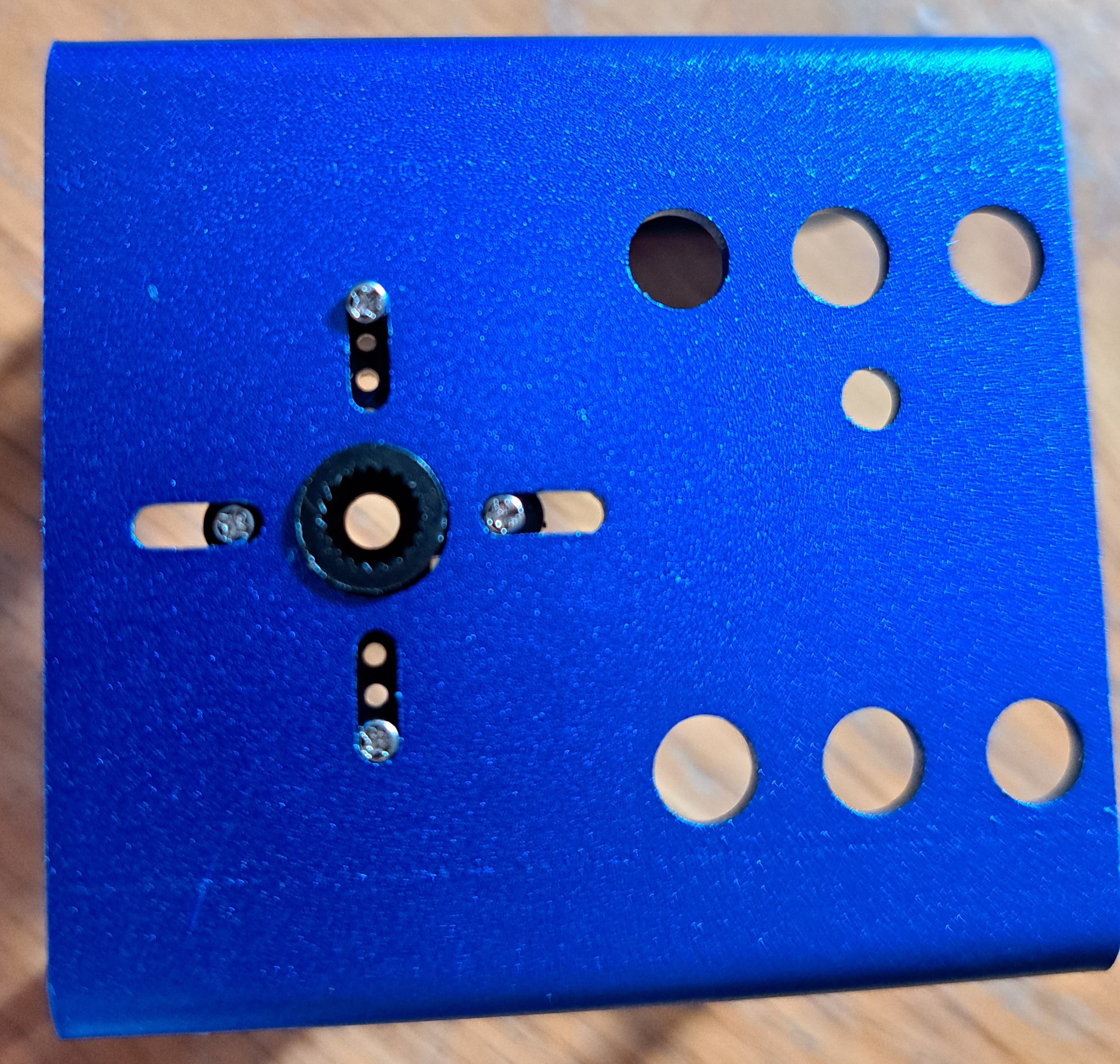
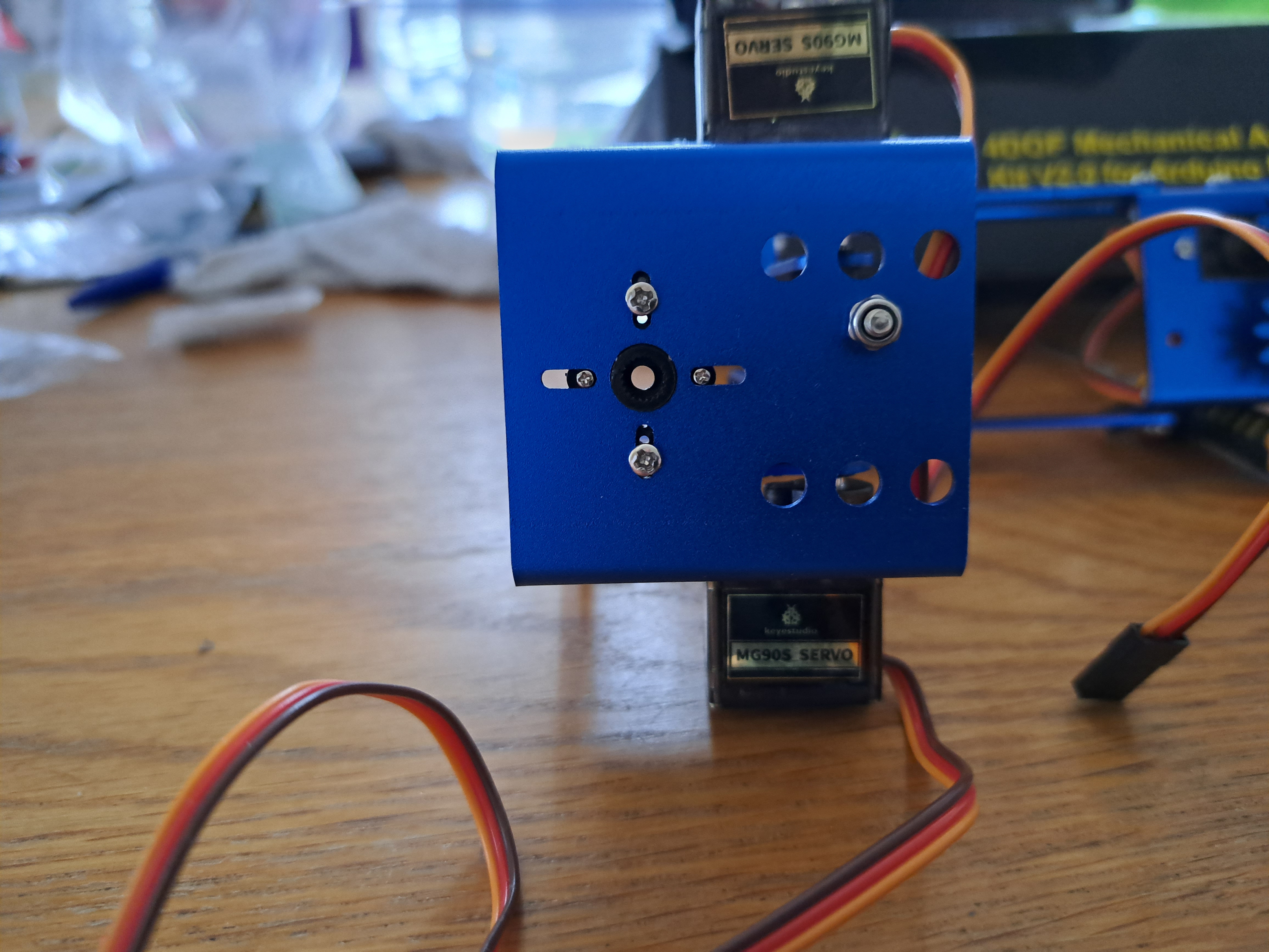
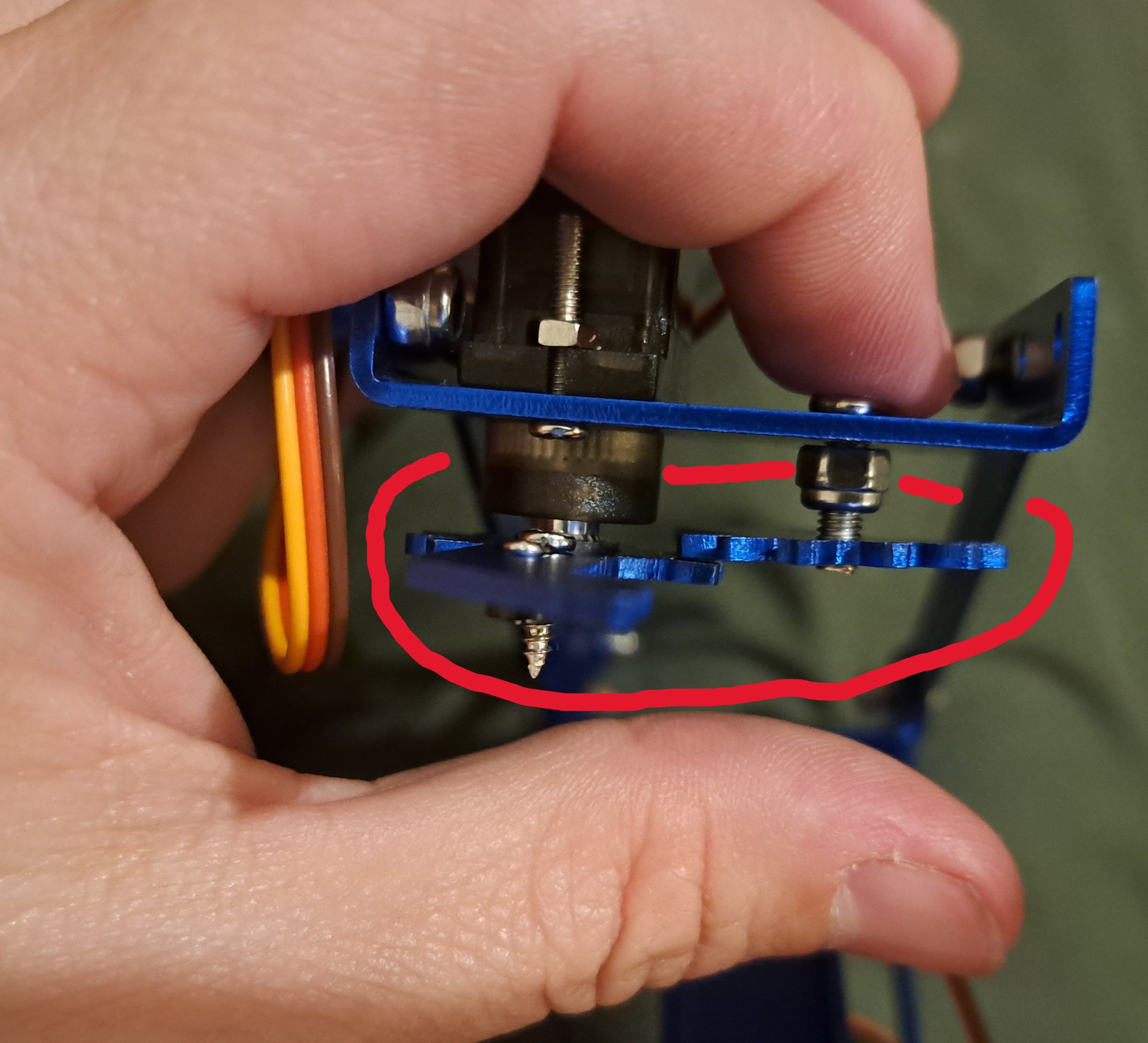
The problems begin with the first step. Four screws are meant to attach each servo horn to a metal sheet. Unfortunately, the metal slots are wider than the tops of the screws, so the screws fall through the metal (first/left figure). After many attempts, I substituted two of the provided screws with slightly bigger screws from a different kit. The slightly bigger screws work really well (second/right figure).
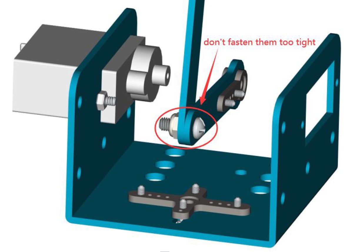
Next, there are multiple screws the instruction manual says not to tighten "too much". I wasn't sure how tight was "too much" so thought I'd give my opinion here: make sure there is space between the two metal pieces so they can move freely past each other. Otherwise the servos won't be able to move the pieces later and the servos will overheat.
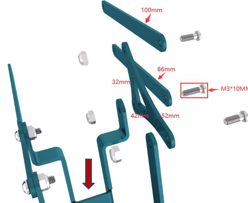
Sometimes many steps are included in a single step (an example is shown below). Including multiple steps at once makes some figures difficult to follow. The figures are even harder to follow when multiple sizes of screws or metal pieces are assembled in the same step.
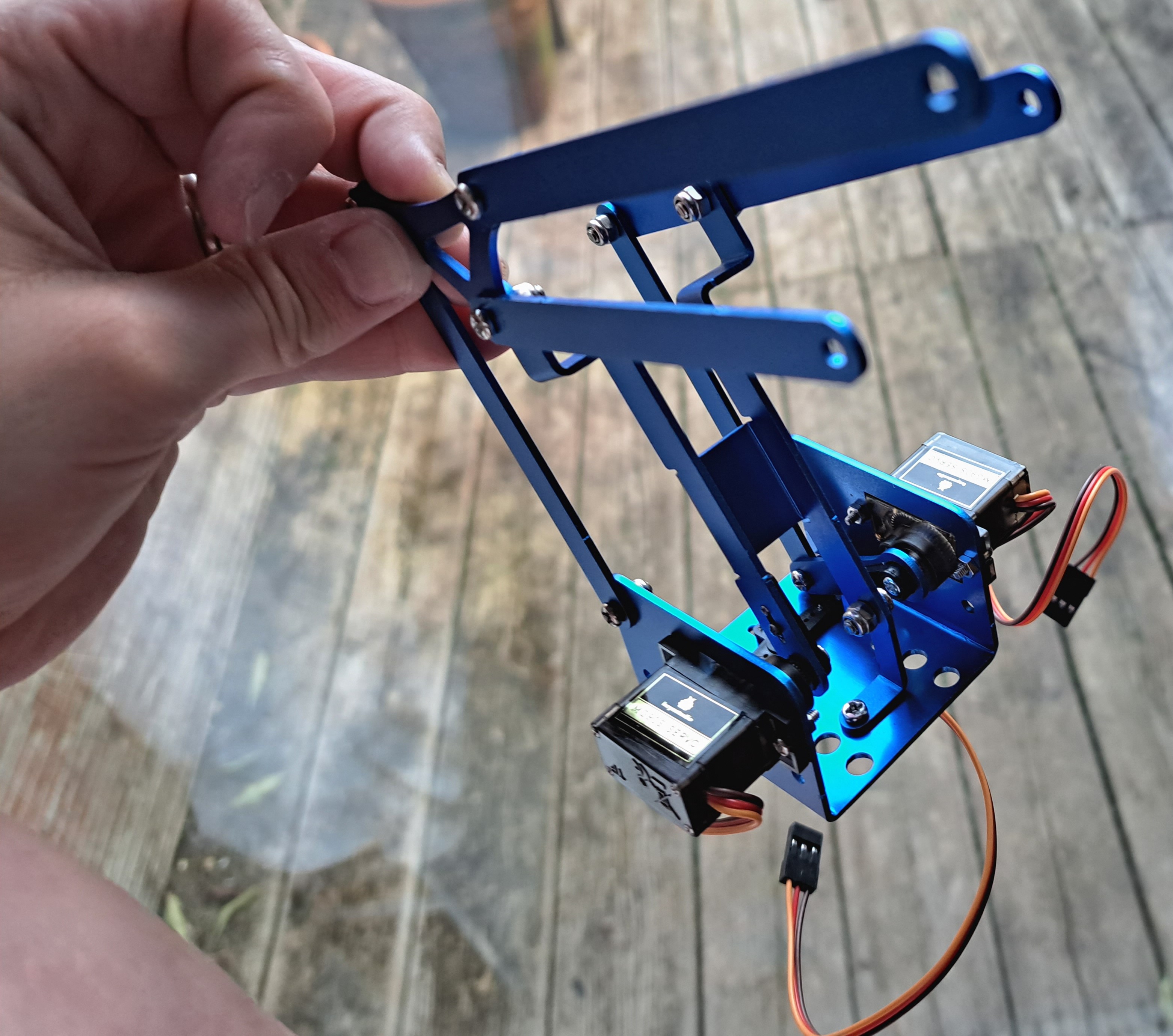
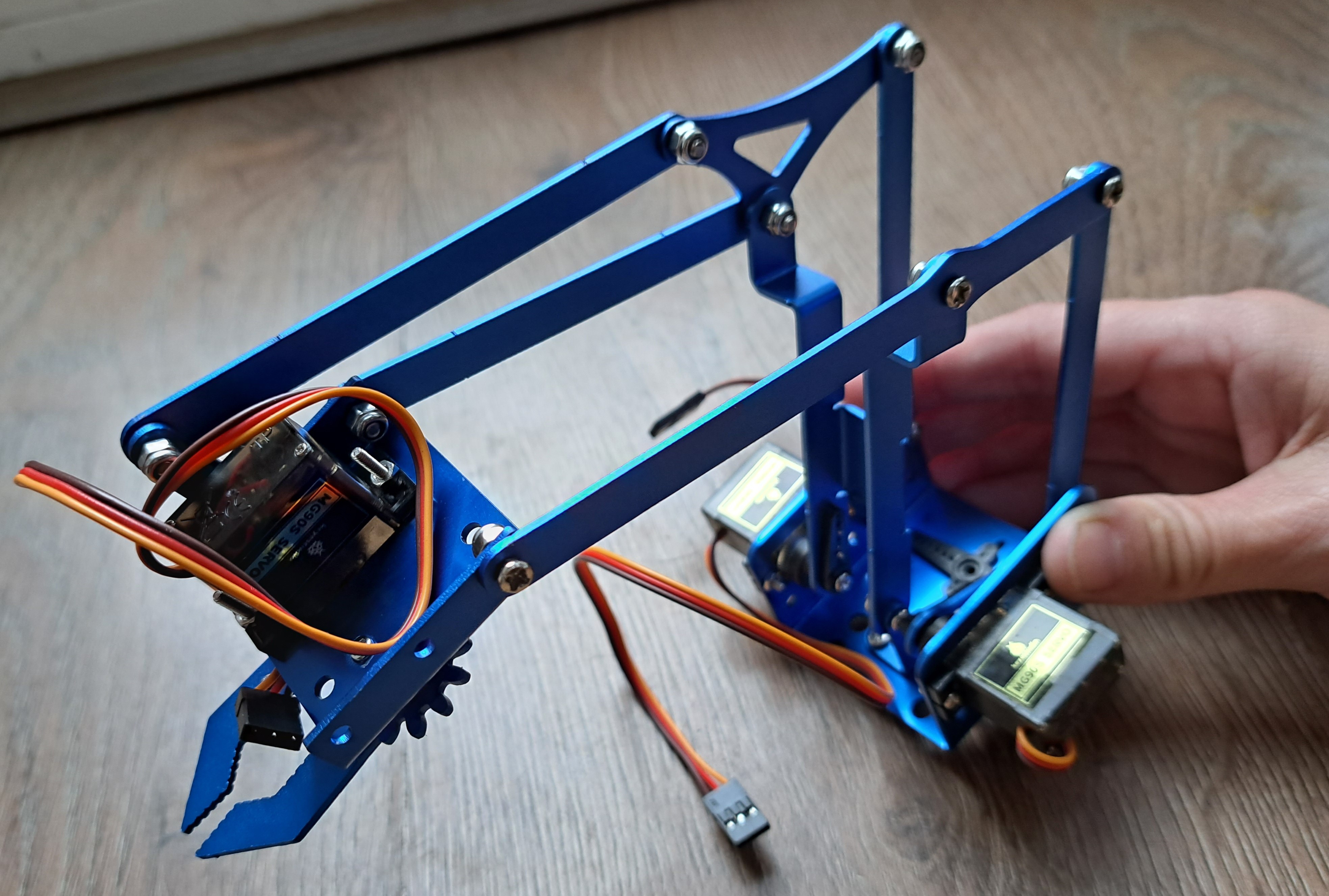
Despite, or perhaps because of, these difficulties, it feels like a major achievement to finish the robot arm crane - even though I wasn't quite sure how these pieces would eventually all come together into a functioning robot arm!
Onto the claw! The claw is one of my favorite parts of the robot arm. A servo opens/closes one side of the claw. The two sides of the claw are intermeshed, however, so the servo actually drives both mirrored sides. How clever is that!?!
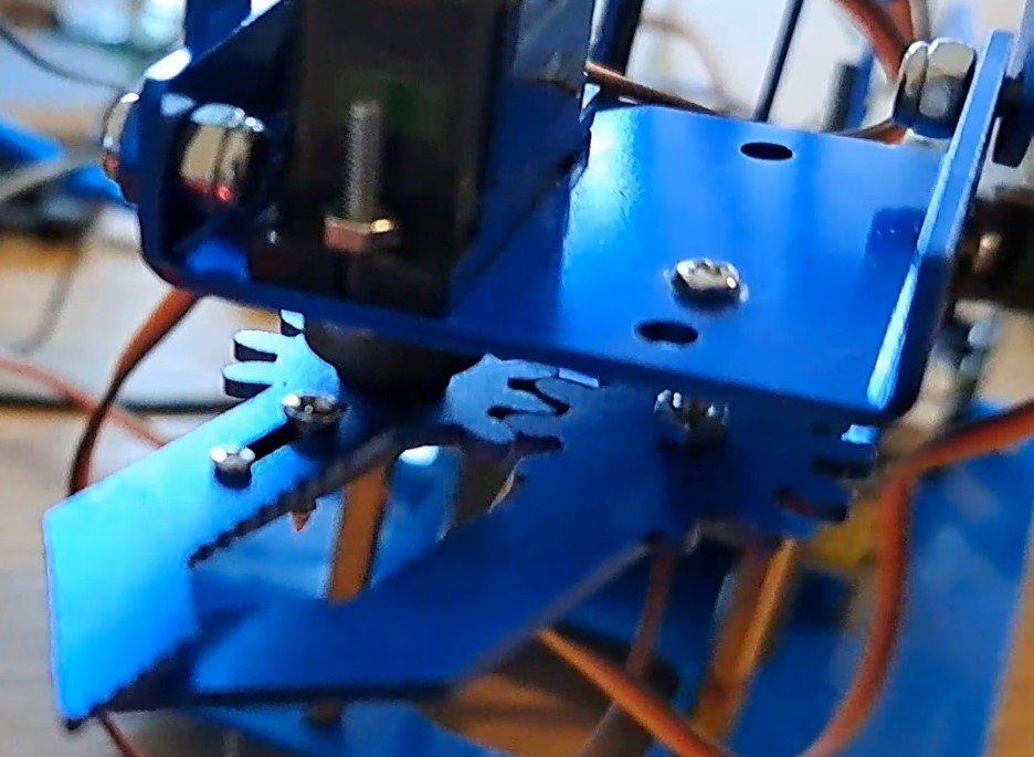
I had 2 issues when making the claw. First, I ran out of the slightly bigger screws from the other kit that I was using to hold the metal pieces and servo horns together. I used the next-smallest screws - these screws look like daggers going through the servo horn! Nothing contacts this area, though, so the length of the screw did not cause any problems. Second and more importantly, the 2 sides of the claw did not physically mesh (first/left figure). The required 3x10mm screw was too short to reach the servo side of the claw. I did not have any longer 3mm screws so used a 2x12mm screw instead, with extra nuts to hold the second claw side in place (second/right figure). This solution works, but the screw/second claw arm moves around and I frequently need to readjust the 2 sides of the claw.
Step 3: Assemble and Wire the Robot Arm
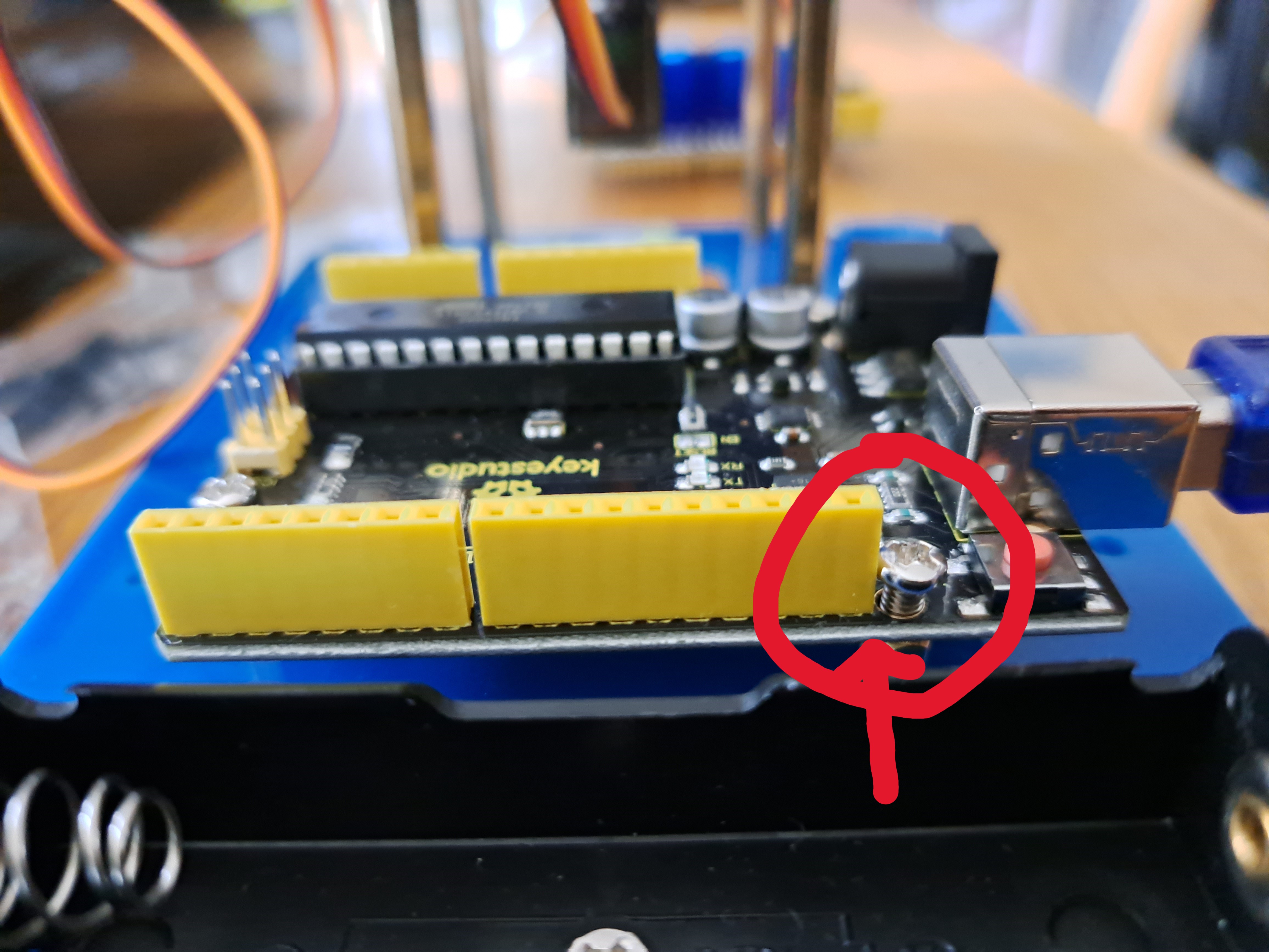
Back to the main/longer pdf, p52!First, push the crane's servo horn onto the base's servo. Then add the Arduino. This is a tight fit so I did not tighten one of the screws much - it still works fine though. Then add the shield on top of the Arduino, and wire the 4 servos into the shield. The manual clearly explains how to do the wiring, and the pins are easy to access.
Step 4: Assemble Joystick Controller and Batteries
The manual clearly shows how to assemble the joystick controller. Unfortunately, my kit seems to be missing the screws and pillars for the joystick. I relocated some of the pillars from under the base onto the joystick controller. I also used various screws from other kits to create the joystick. The manual also clearly shows where the controller wires need to go. It is tight squeezing the connectors onto the Arduino shield.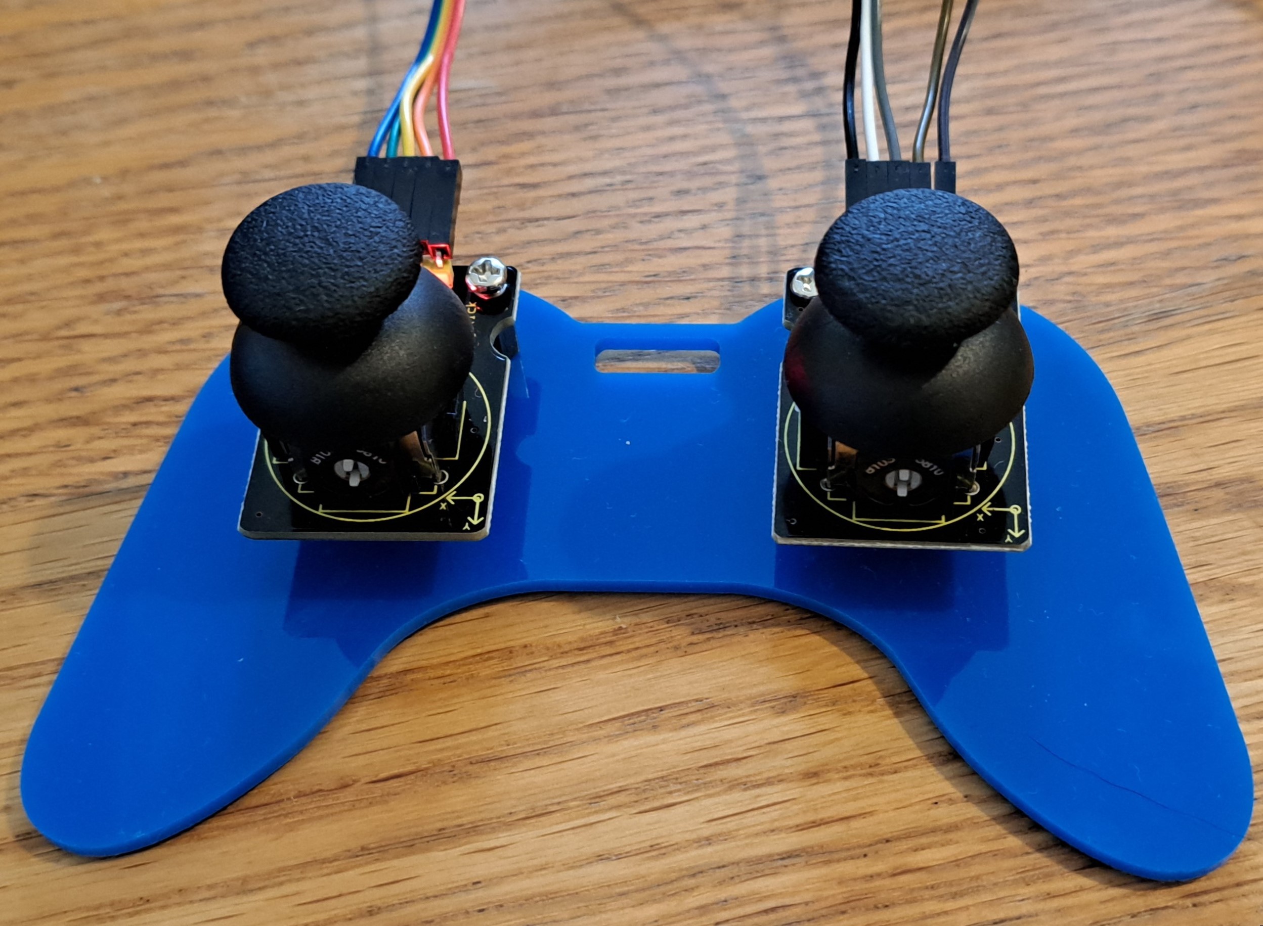
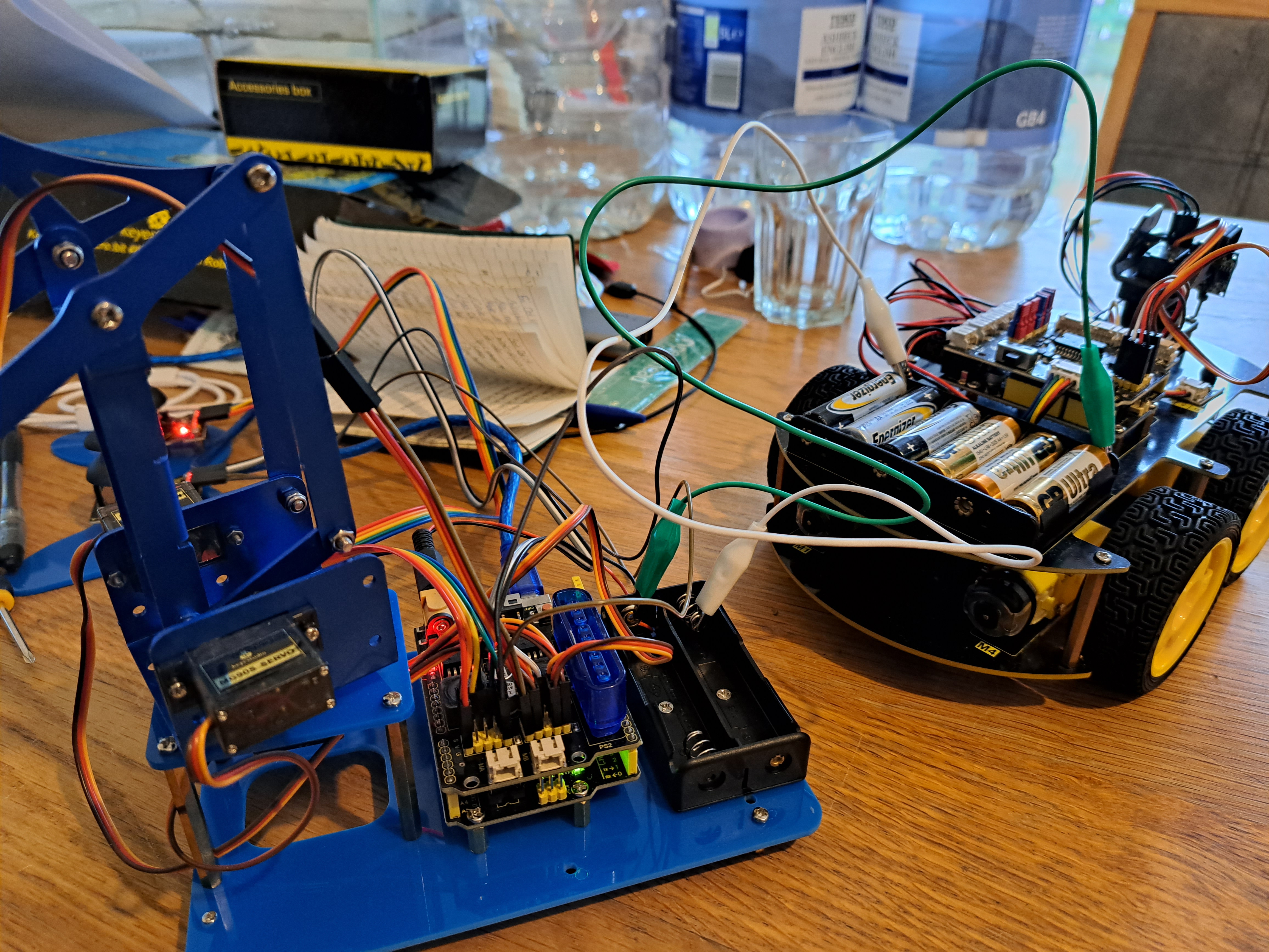
The robot arm and joystick are powered by batteries. The kit says to use 2x18650 batteries. 18650 batteries are hard for me to source, however, so I alligator-clipped in 6xAA batteries from my Arduino car instead.
Step 5: Use the Robot Arm
The robot car can be controlled by the joystick controller or by Bluetooth in a downloaded App (or, optionally, with a PS2 controller [not provided in kit]).The joysticks are fun, but I struggled to remember each joystick's functions so I have listed the functions below. In general, the left joystick controls the claw and its platform - the right joystick controls the arm.
Left Joystick
Move to left: Close Claw
Move to right: Open Claw
Move to up: Claw Platform Goes Up
Move to down: Claw Platform Goes Down
Press: Go to Saved Position
Right Joystick
Move to left: Arm moves to left (if directed away from you)
Move to right: Arm moves to right (if directed away from you)
Move to up: Stretch out arm
Move to down: Bring back arm
Press: Save Position
In addition to manually moving the robot arm, multiple robot arm positions can be saved and then looped through to make the robot arm perform specific actions. This feature lets the robot arm be programmed like it might be in a manufacturing plant to load/move items.
Similarly, the App is fun to use but not intuitive. For example, the App has a pair of up-down buttons, but the up button makes the platform go down - and the down button makes the platform go up! There are also buttons for "Mode 1" and "Mode 2", but we are not told what these modes do. Also, note that the robot arm only moves one, small increment each time the button on the App is pushed. Tapping and holding the App's button does not make the robot arm continue moving. Many pushes/releases are required for large motions in the robot arm.

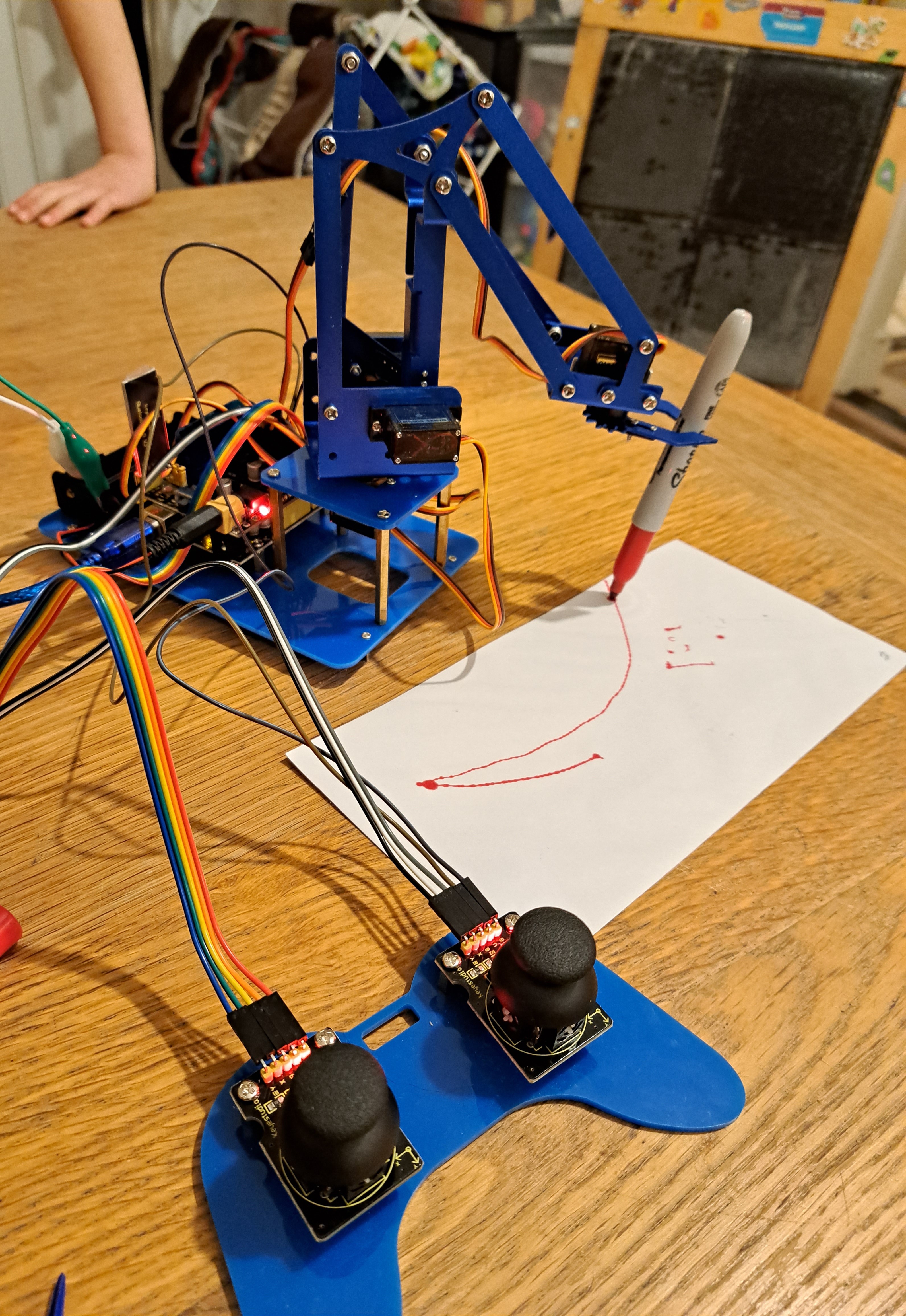
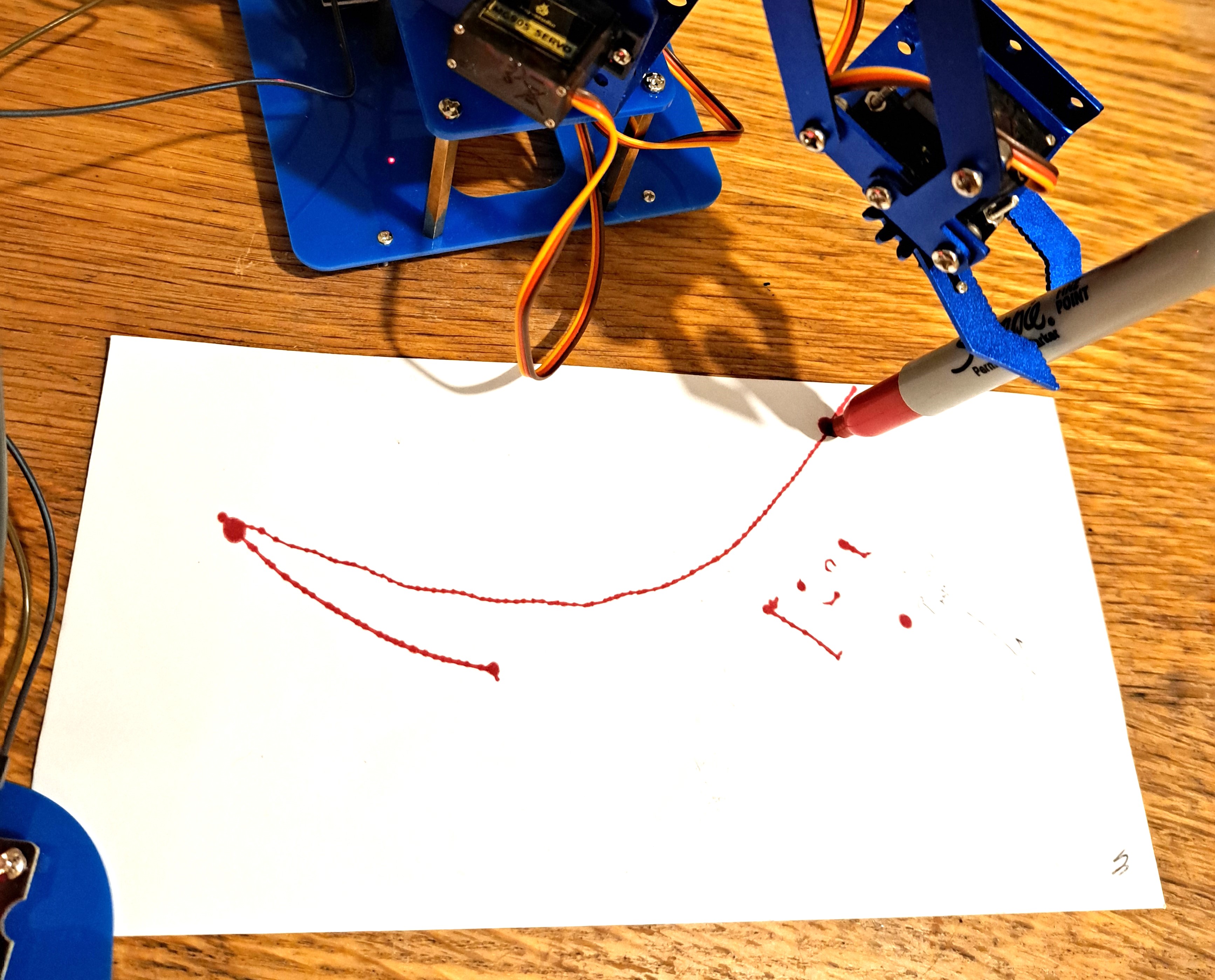
I used the App to draw on a piece of paper with a Sharpie marker. First, I set the marker between the two sides of the claw. Then I closed the claw around the marker. This took multiple tries as closing the claw too far/tight made the marker pop out. I got a better grip on the marker by angling the marker. Then I rotated the arm left and right in an arc. I had to continually tap the App to create this motion. The arm stopped between each tap - resulting in juts along the arc.
I did not try controlling the robot arm with a PS2 controller.
A Final Overview!
Things I really liked:-Learning how each of the 4 servos control robot arm motion.
-Being introduced to idea of intermeshing 2 claw sides with a single servo - genius!
-Being able to save and loop positions of robot arm.
-Having 2 (optional 3) ways to control the robot arm - I love using the joystick controller!
-Drawing with the robot arm - very fun!
Things I suggest improving:
-Checking all required screws/pillars/etc are included and correct sizes.
-Using AA rather than 18650 batteries.
-Combining 2 instruction manual pdf's to become 1 manual.
-Including new project where user specifies arm locations and robot arm moves to locations.
-Changing App so that continuing to tap/hold a button means motion continues in that direction.
This kit builds a robot arm and joystick controller, which are very fun to use! The kit I got required significant troubleshooting, however, so would be better for experienced rather than novice electronic kit users. Keyestudio is currently checking to see if other kits also have missing/incorrect parts - or whether I was just unlucky. Overall, I am pleased with the kit, especially once I could start drawing with it (drawing would be even better if the second claw was tighter / had correct screw)!
Other Articles:
|
Moon FormationA Kotlin N-Body code, and lots of animations of the collision between Earth and a hypothetical Theia that people think created the moon. |

|
Atomistic Simulation of MetalsThis presents an interactive simulation of atoms making up a nanoscopic particle of metal. |
© Hugo2015. Session @sessionNumber