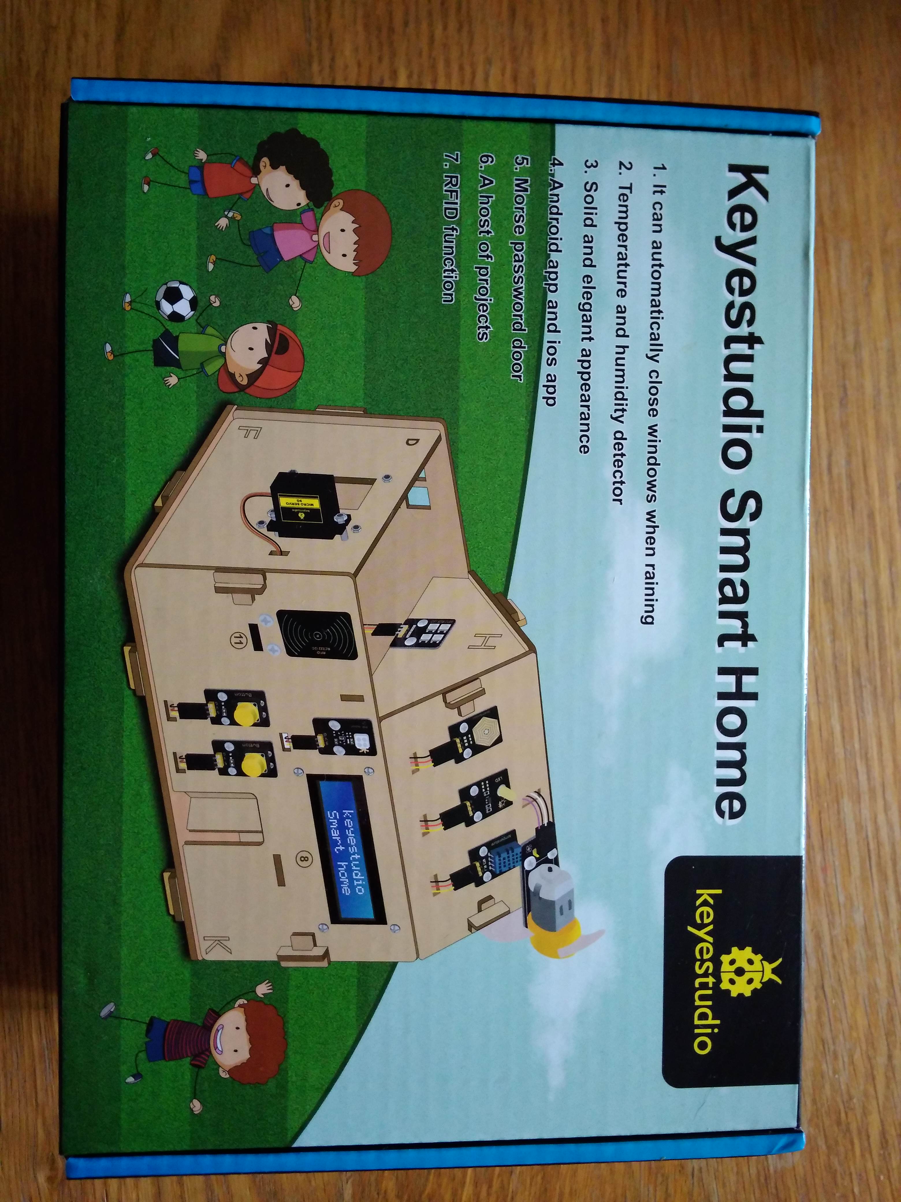
Review of Keyestudio's Smart House IoT (ESP32 version: KS5009)
By Dr Jennifer Martay PE, Course Leader for Medical Engineering at Anglia Ruskin University
I have recently been expanding my arduino skills - and Smart Cities and Houses are key themes within my School.
Therefore, when I saw this Smart Home IoT kit, I bought it as a way to extend my skills.
What did I think about it? In short, I definitely learned. Some parts of this kit I loved, and some parts were very frustrating. Keep reading for more details.
First Impressions
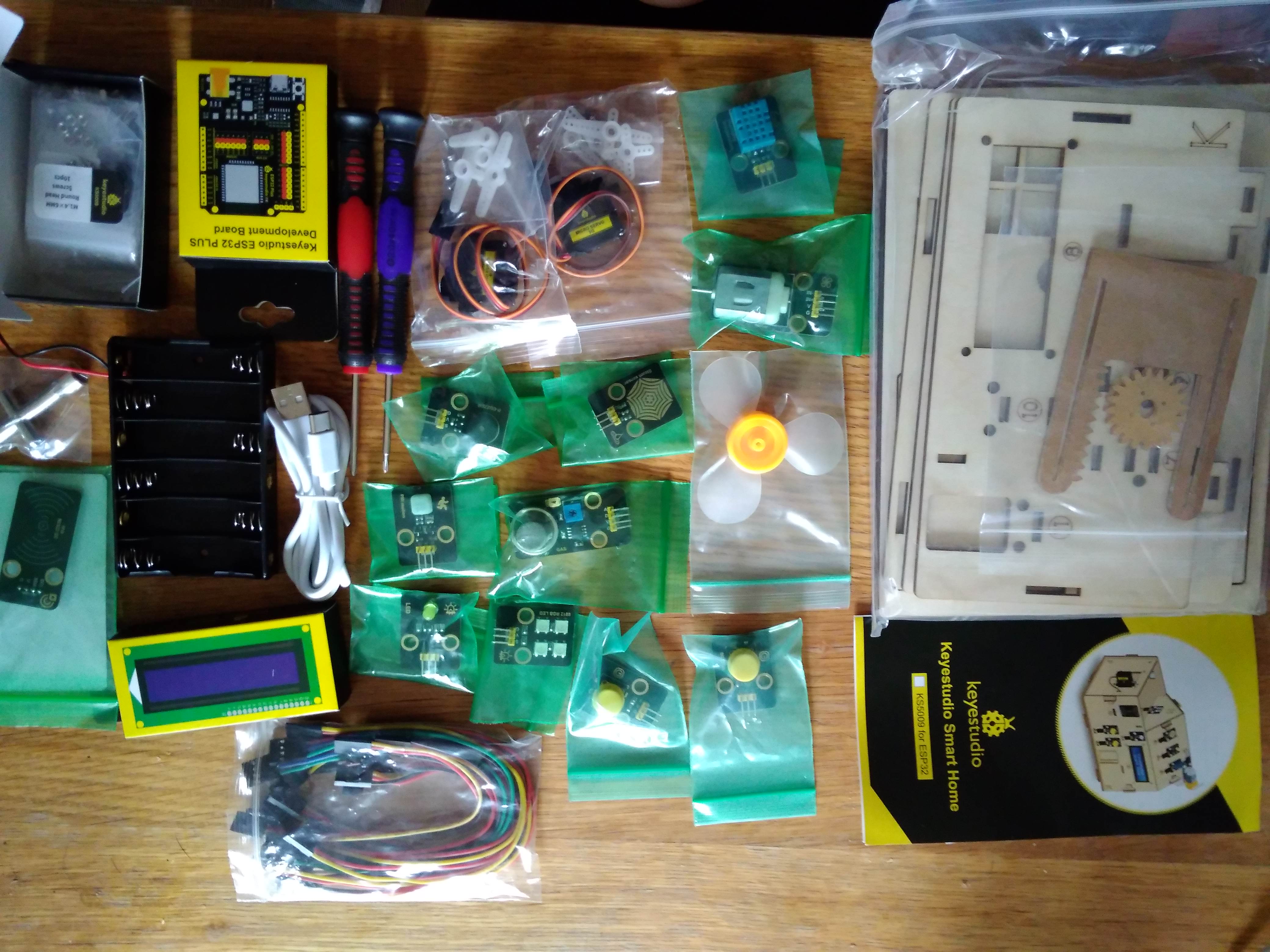
The box is absolutely jam-packed (literally!) with components. I really don't think it'd be possible to add anything else. Each part was identified in a booklet, though this wasn't necessary as the names are also printed on the components. The parts seem good quality, and I was particularly pleased with the laser-cut wood house frame. I was disappointed by the number of little plastic bags - not great for the environment.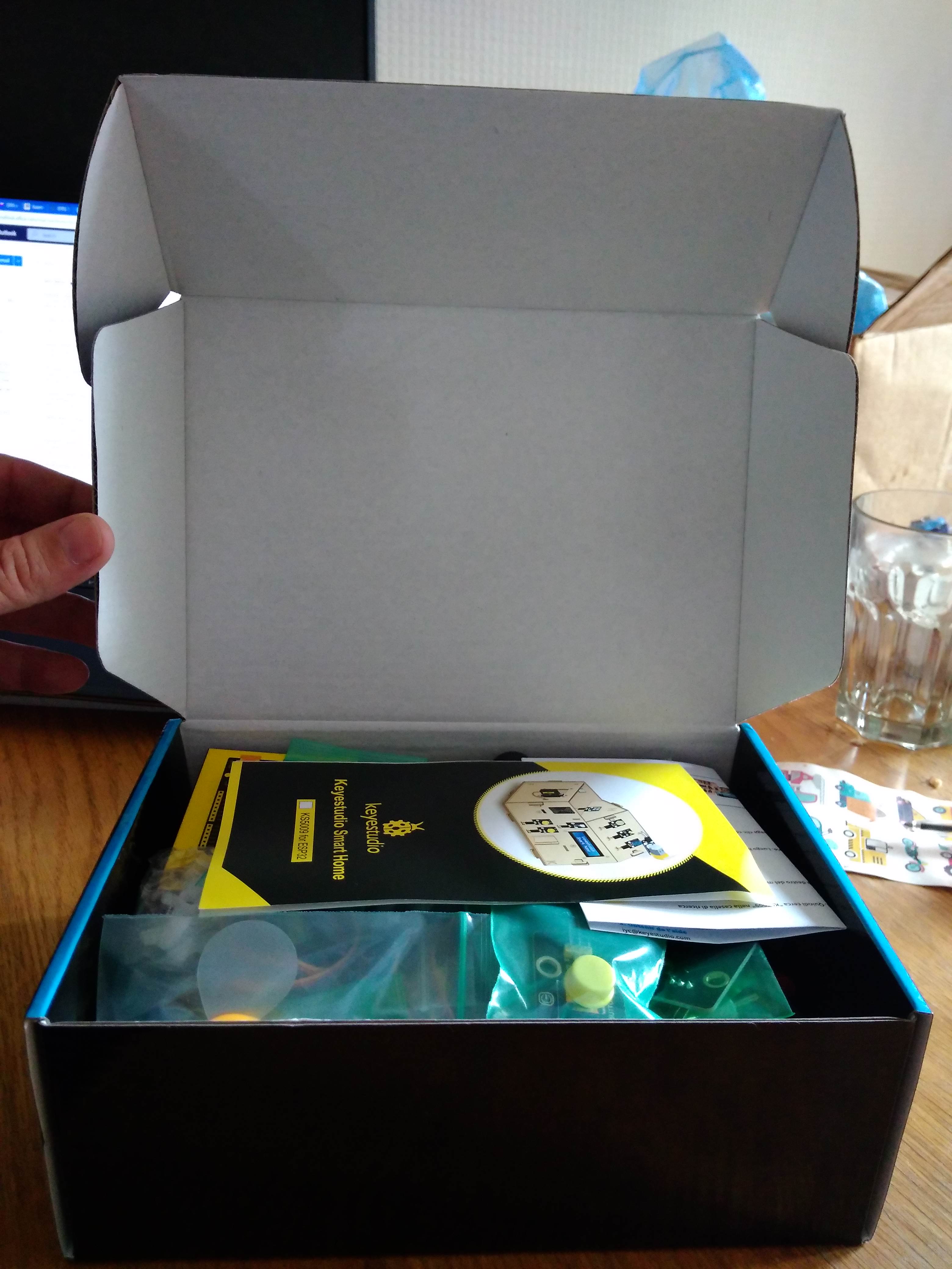
Day 1: Building a House / Finding the Instructions
I didn't have a lot of time on Day 1 so decided my goal would be putting together the house's frame. I couldn't find any instructions but managed to piece the house together like a puzzle. I was proud when I finally got the house together. Then I was annoyed when I found the instructions and realized I'd have to take the whole house apart to put the components on. The instructions were hidden on a tiny piece of paper and take you to this website which redirects you to a dropbox folder. Use the word doc at the bottom - it's very detailed (once you find it!).
Day 2: Adding Components to House Panels
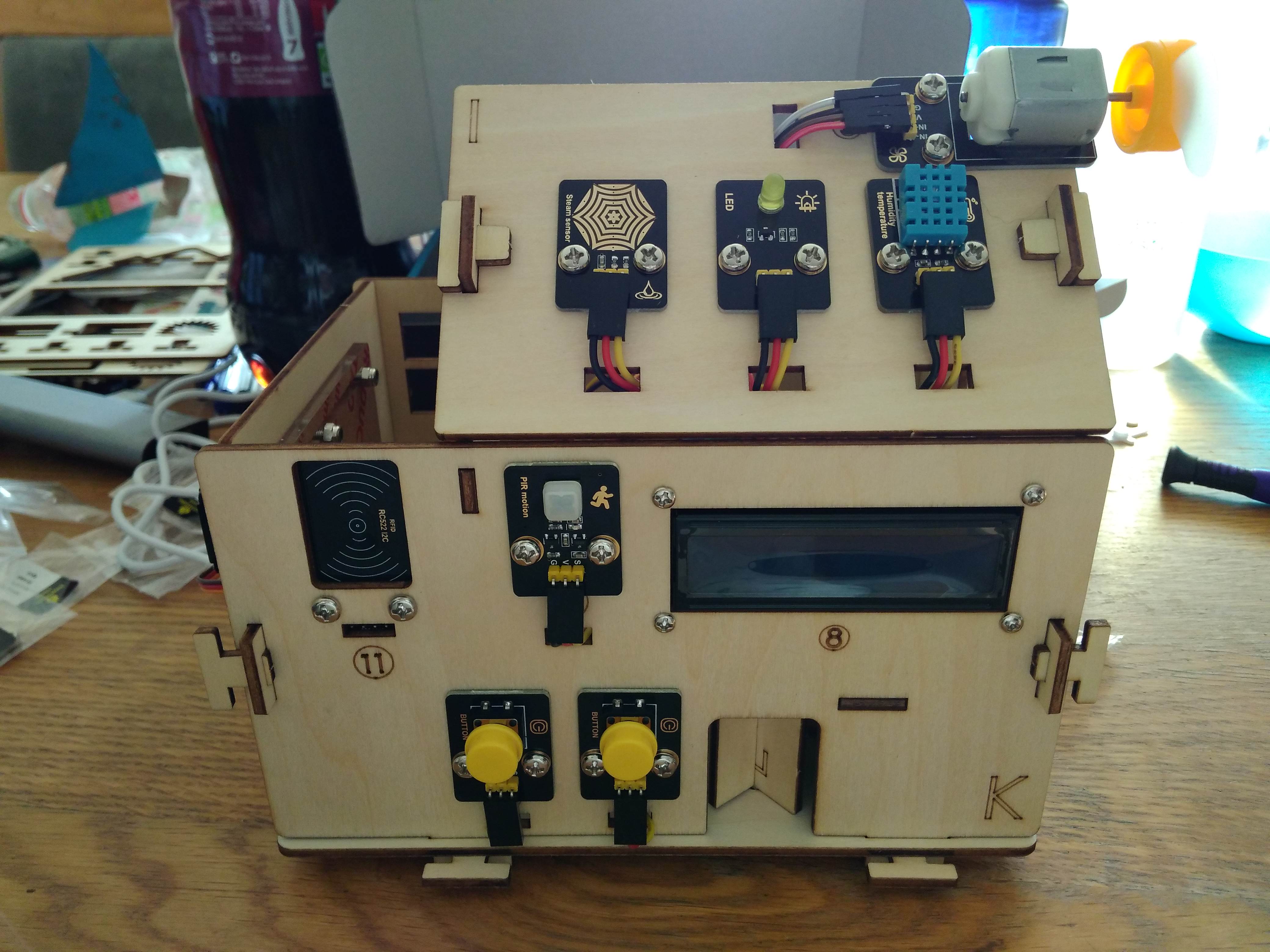
The User Guide clearly indicated where each component goes. Each frame is labelled with an alphabet letter; each component is named.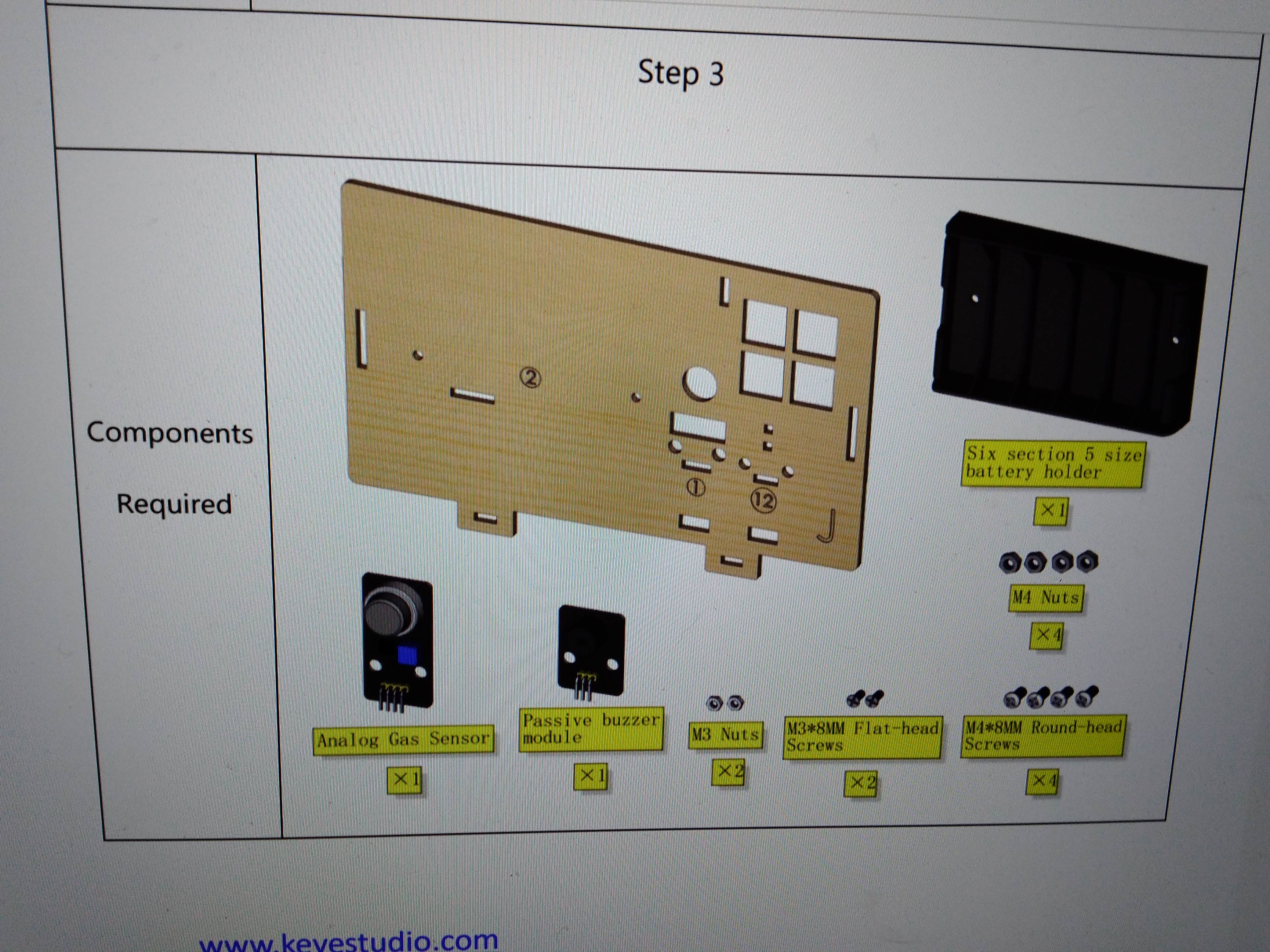
It was quick and easy to put the different components onto the various panels of the Smart House.
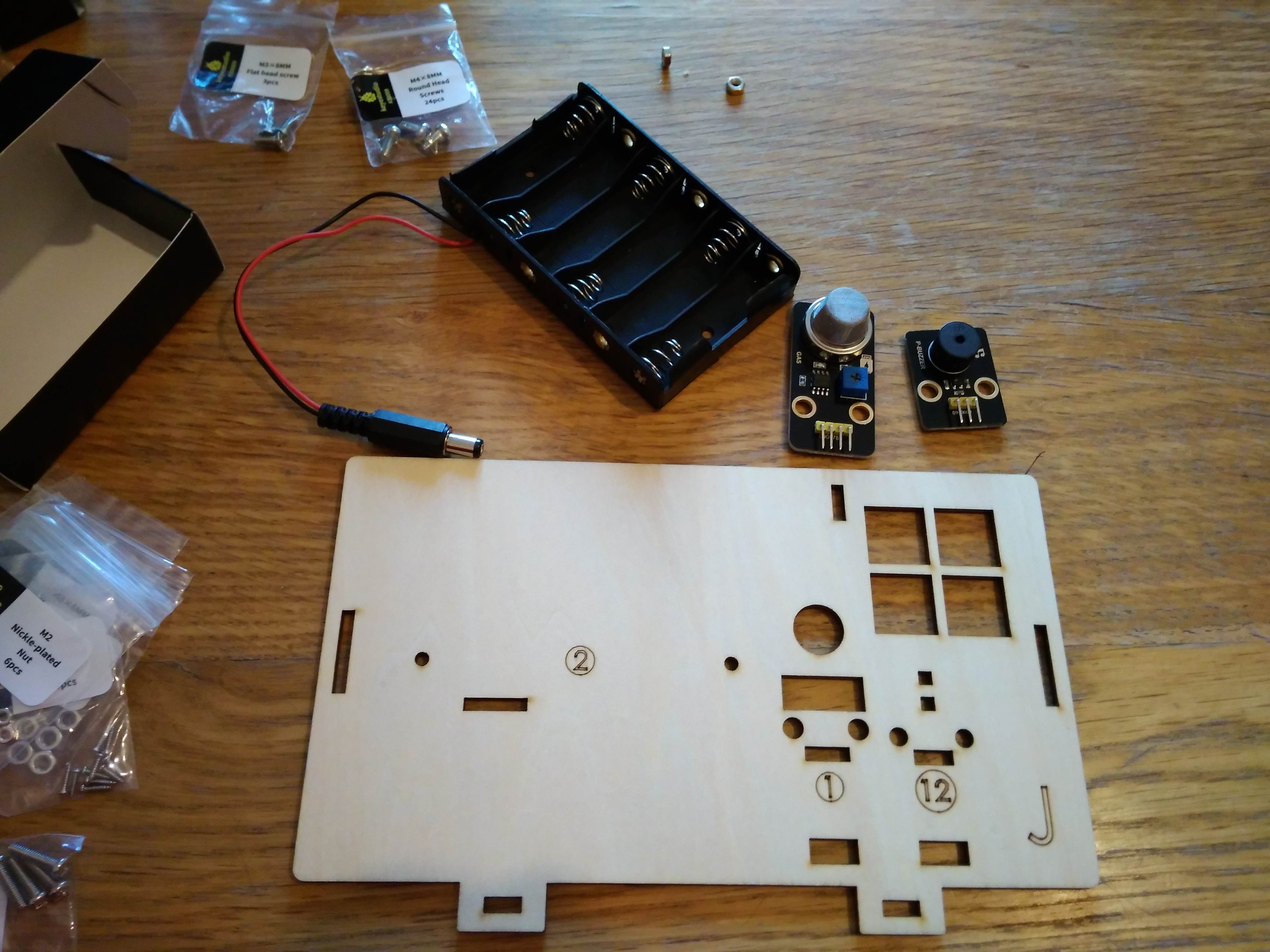
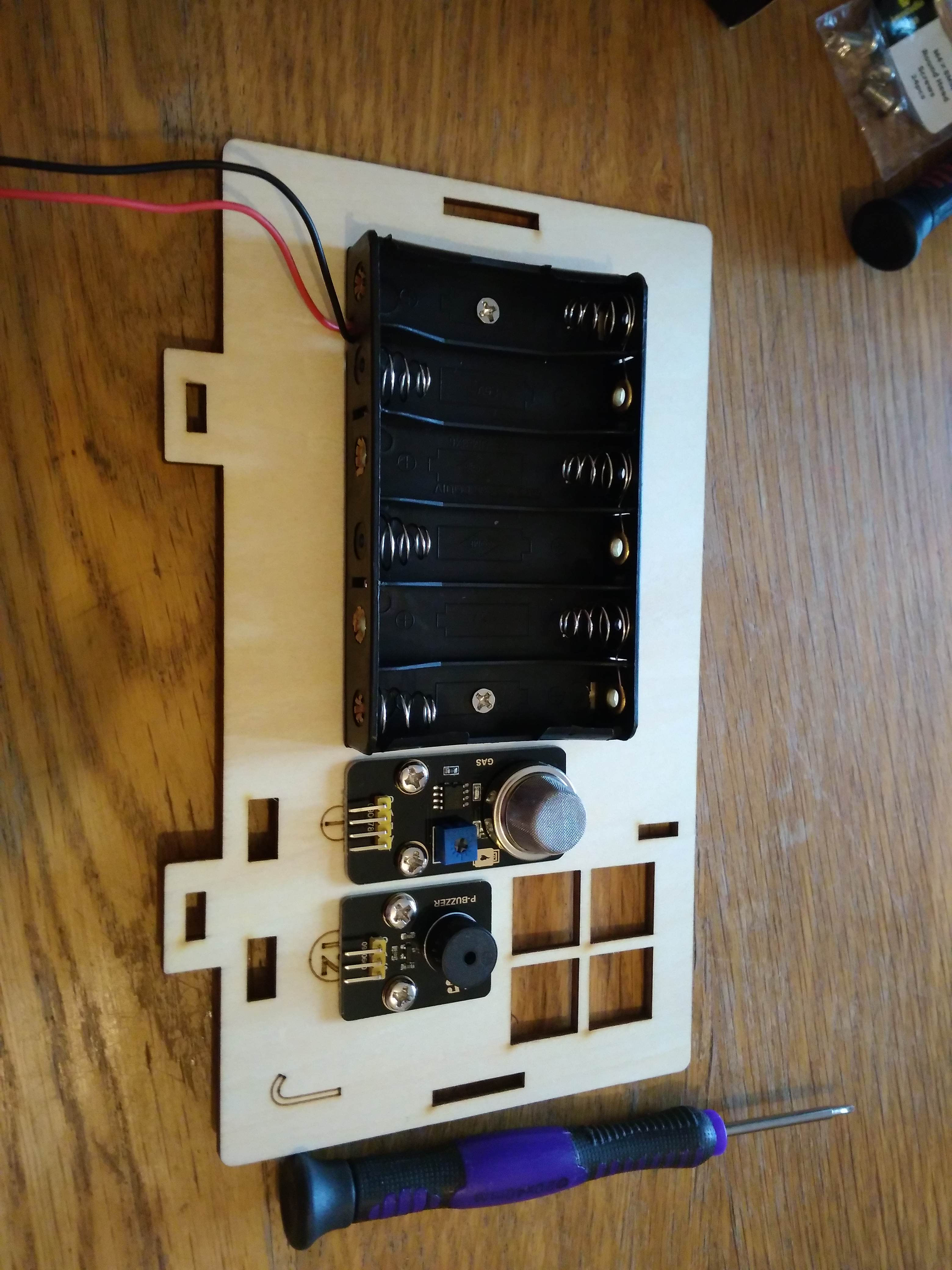
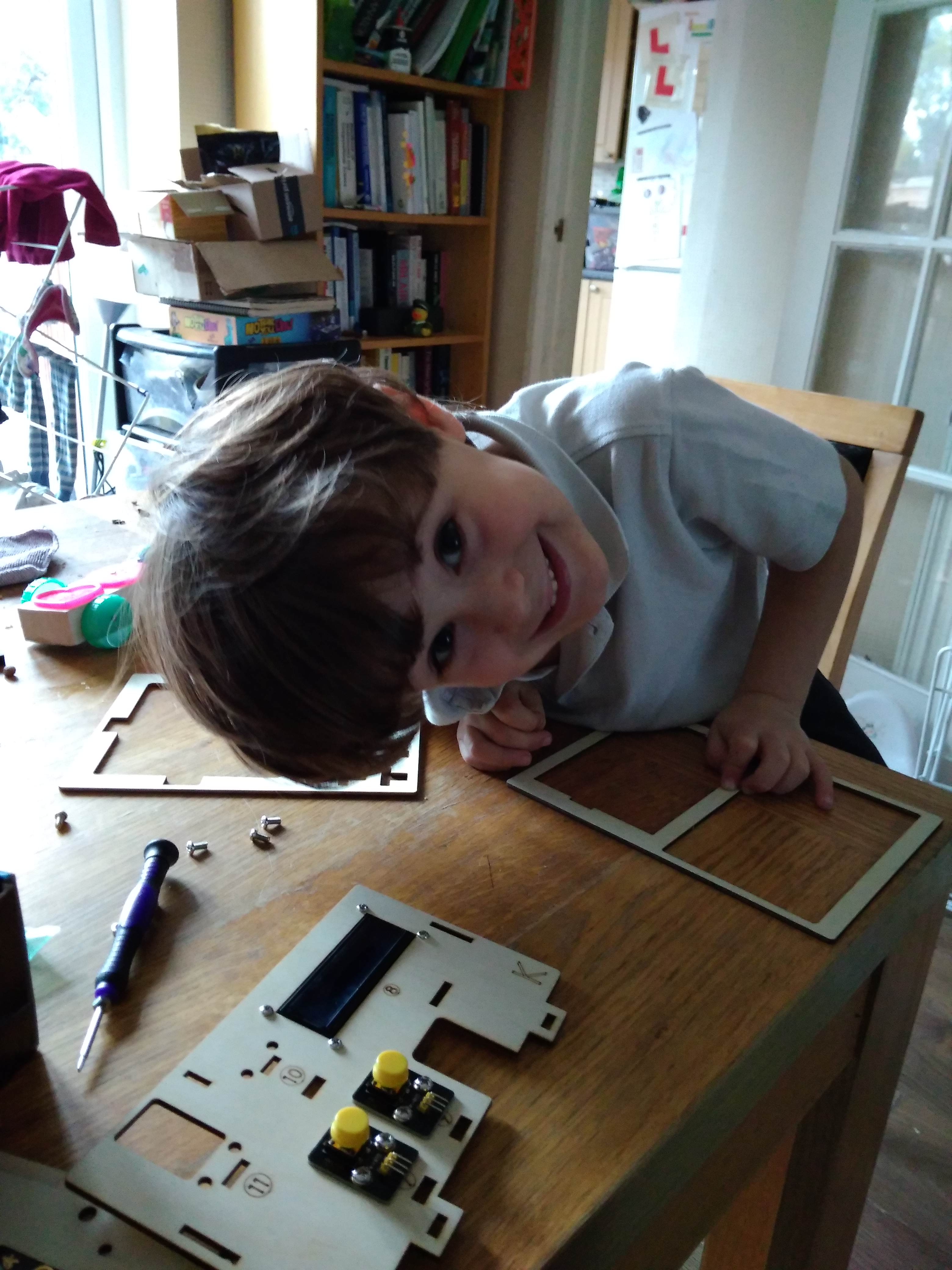
My 4-year old really enjoyed this day, especially identifying letters, looking at all of the sensors, and using the magnetic screwdrivers!
Day 3: Fighting with the ESP32 Plus Board
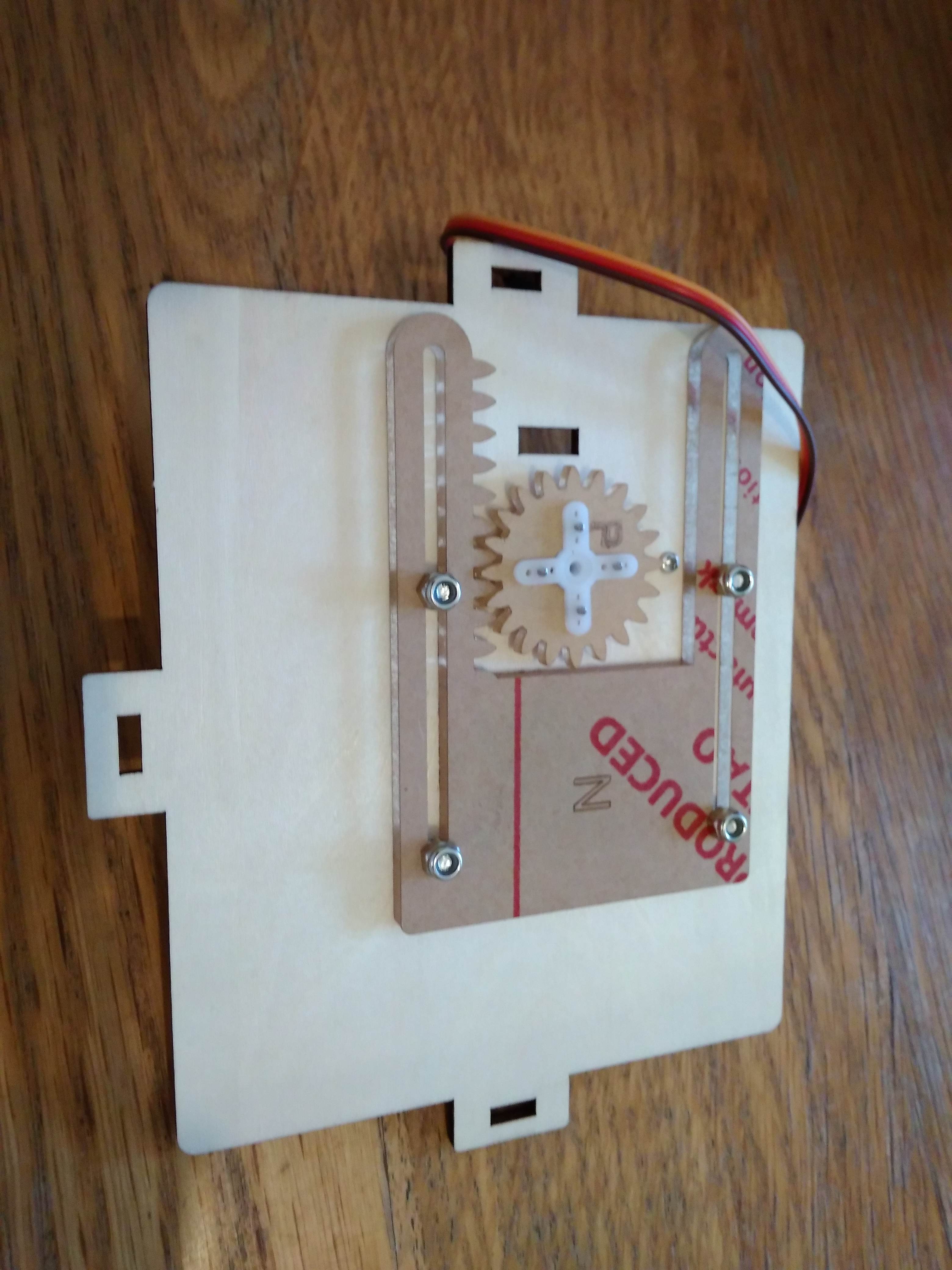
This kit uses an ESP32 Plus board. The ESP32 board powers a servo located underneath the gear in the picture above. This gear opens and closes a window on the Smart House.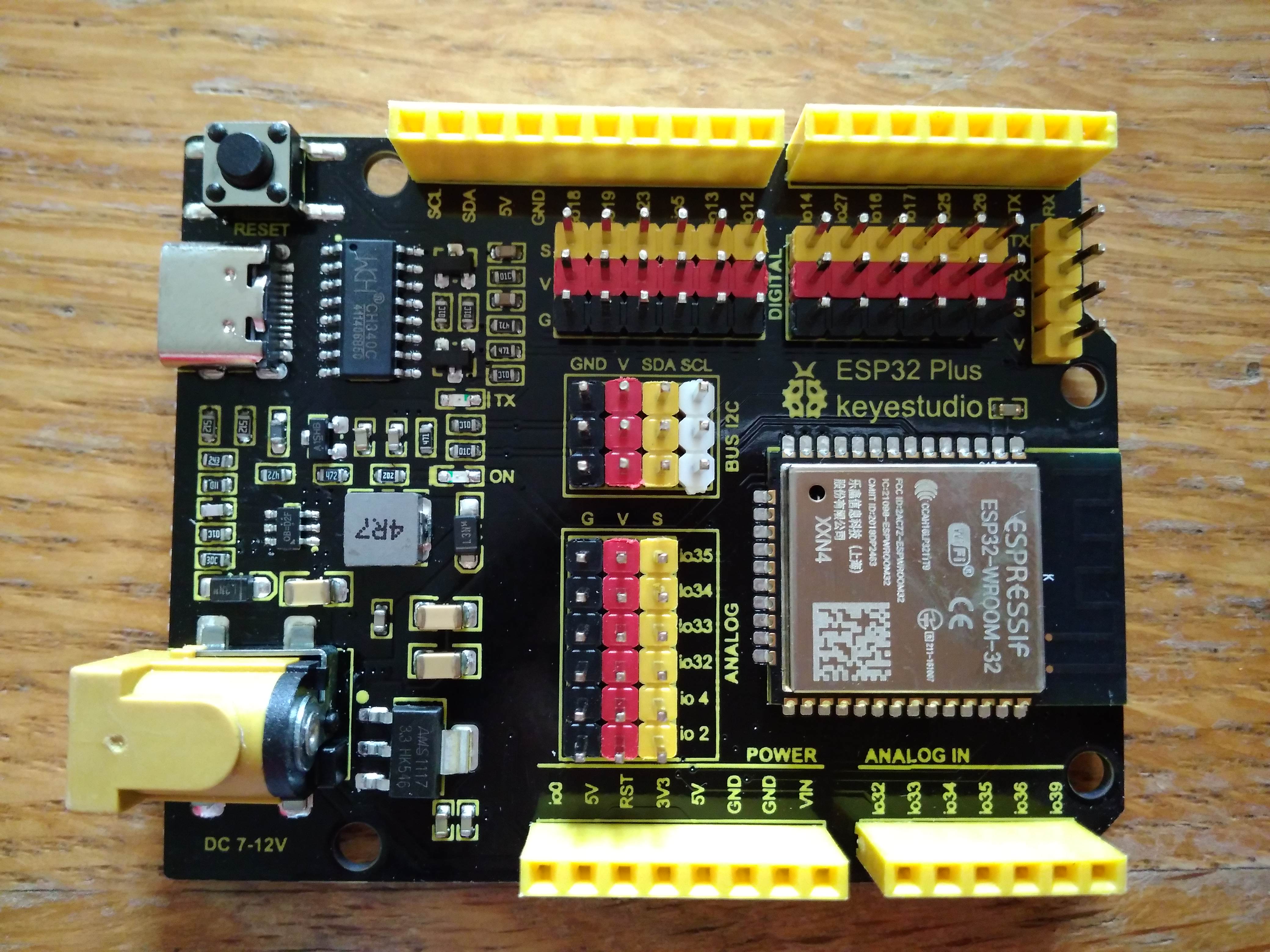
Buyer beware: ESP32 is NOT the same as Arduino Uno, no matter what the documentation says!
Pros of ESP32: I love the triplets for ground-power-signal. Much easier than fighting with each wire individually. ESP32 is also meant to be more powerful and allow bluetooth and wi-fi.
Cons of ESP32: Nothing worked, at least at first. I changed ports and boards countless times based on the user guide. Still nothing worked. Eventually I installed the ESP board into Arduino IDE using this website. Now I could talk to the board! My arduino experience teaches me to next try "Blink", which didn't *appear* to be working. Hours later, I realized ESP32 doesn't have a built-in LED like the arduino uno. I set up my own LED circuit to prove the ESP32 board was working. Never been so happy to see a blinking LED! This process took an entire day, however, and was incredibly frustrating!
Overall: I learned loads that I hadn't expected, which can be painful at times. Still, it's learning and that was the point of the project!
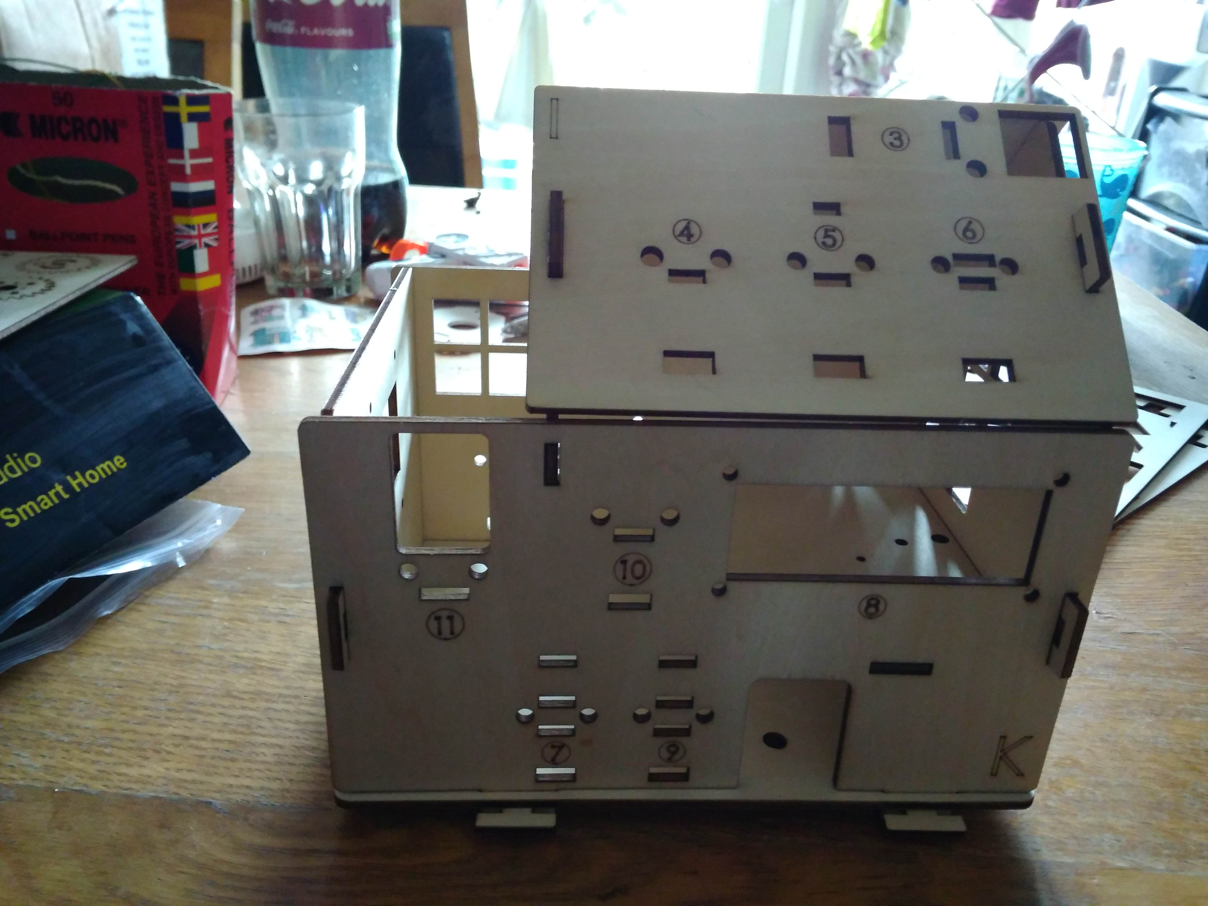
Day 4: Assembling Smart House and Wiring Up Sensors
Assembling the Smart House panels was generally fun and easy. The hardest parts were inserting the thumb pieces that hold together the different house panels and assembling the rotating door. As you can see in the picture above, I didn't completely push in the thumb pieces that hold the panels together. I was afraid they would break if I pushed any harder. Two pieces also slotted together to create the rotating door (can't be seen in picture). The door only fit in the house if the two pieces were pushed completely together. I had to push incredibly hard to slot these parts together - and then one end of the pieces actually exploded... Luckily the door still seems to work! Keyestudio could fix these issues by allowing larger gaps in places where parts need to fit together.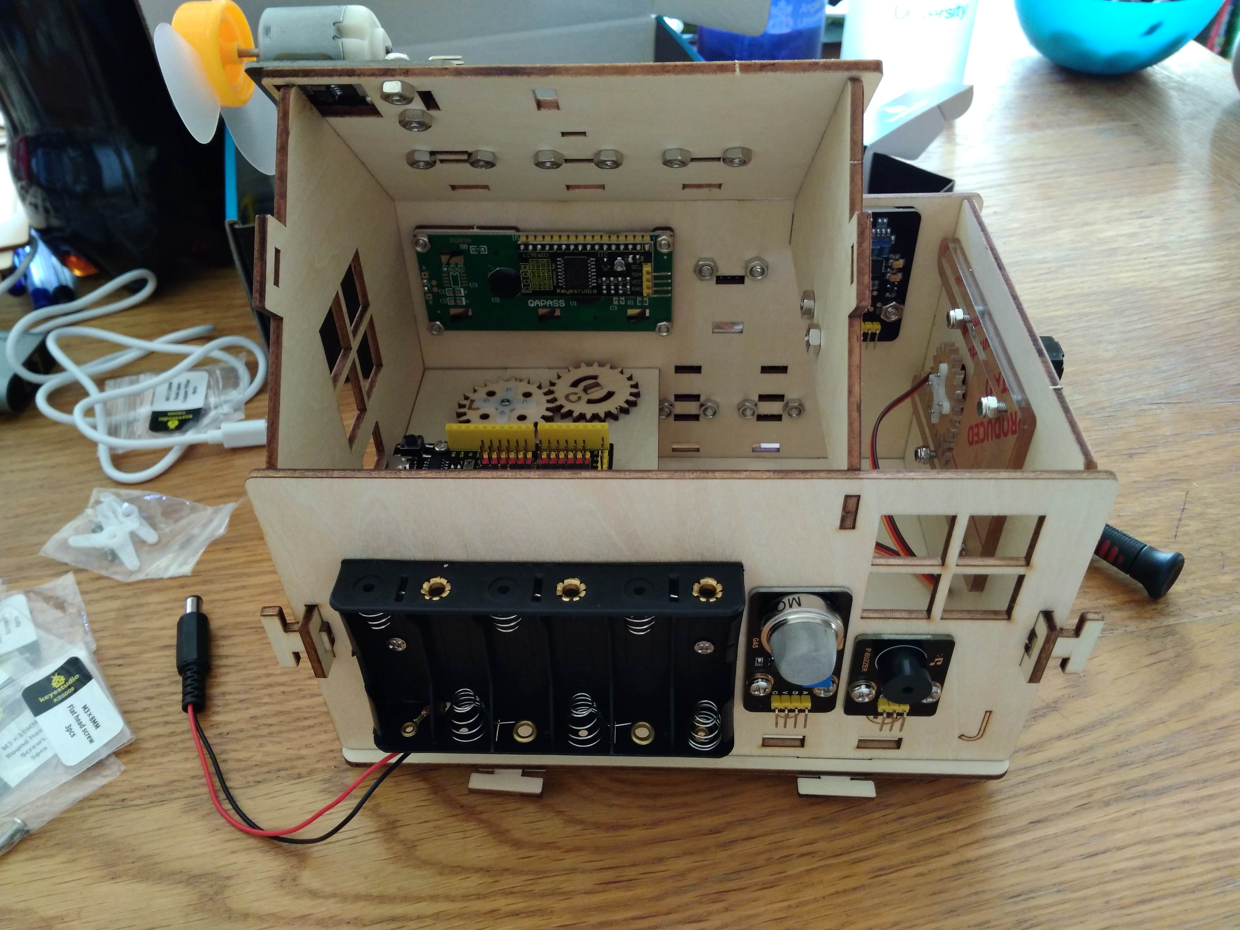
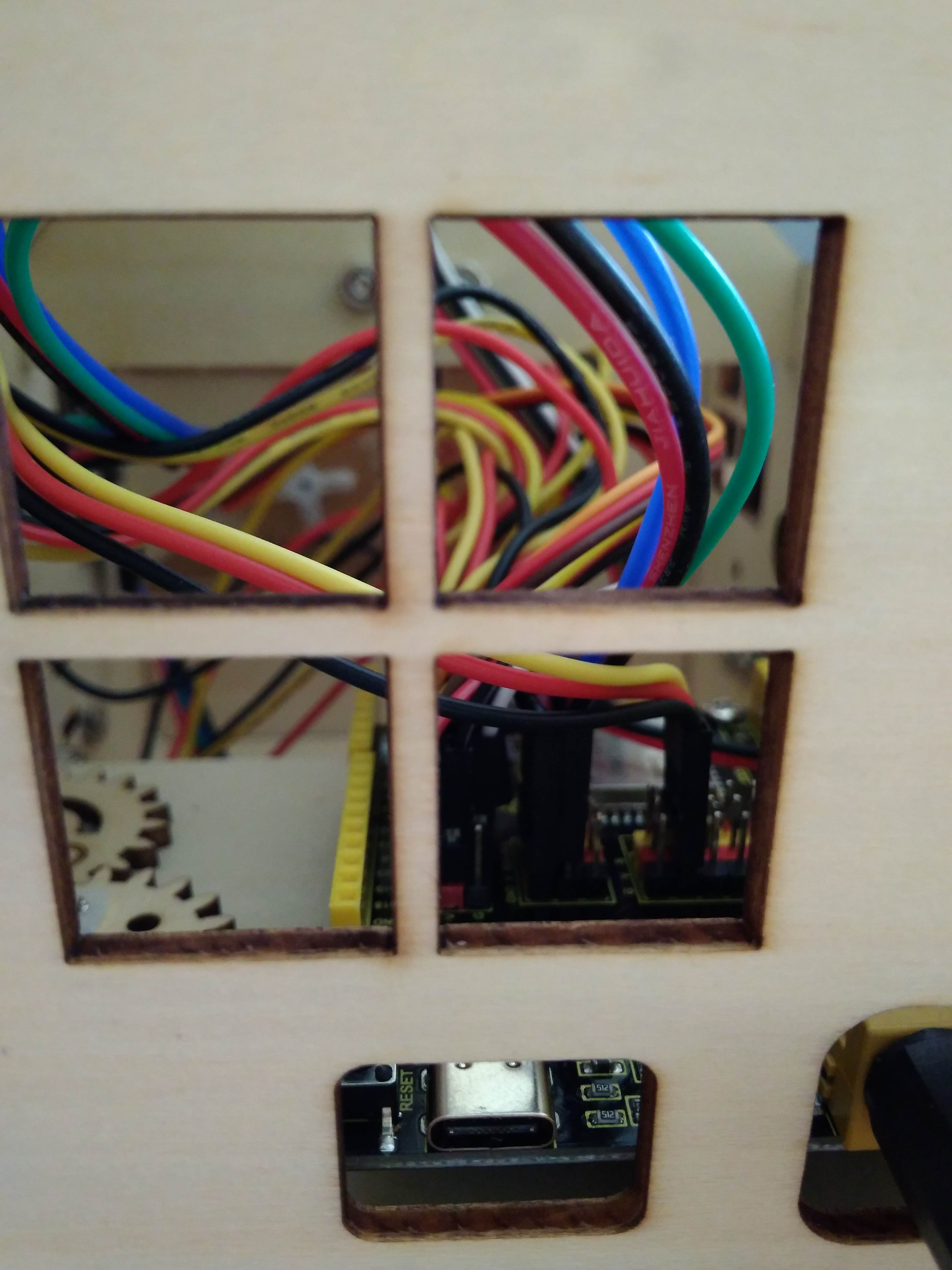
Next, I wired up the sensors. The user manual explained the wiring step-by-step and was very easy to follow. The wires themselves ended up very close together, making it hard to check the last few were in the correct positions and slotted correctly into V-G-S (not accidentally missing one of the pins). If I were to do this again, I'd twist each triplet of wires together to make them easier to see and keep together.
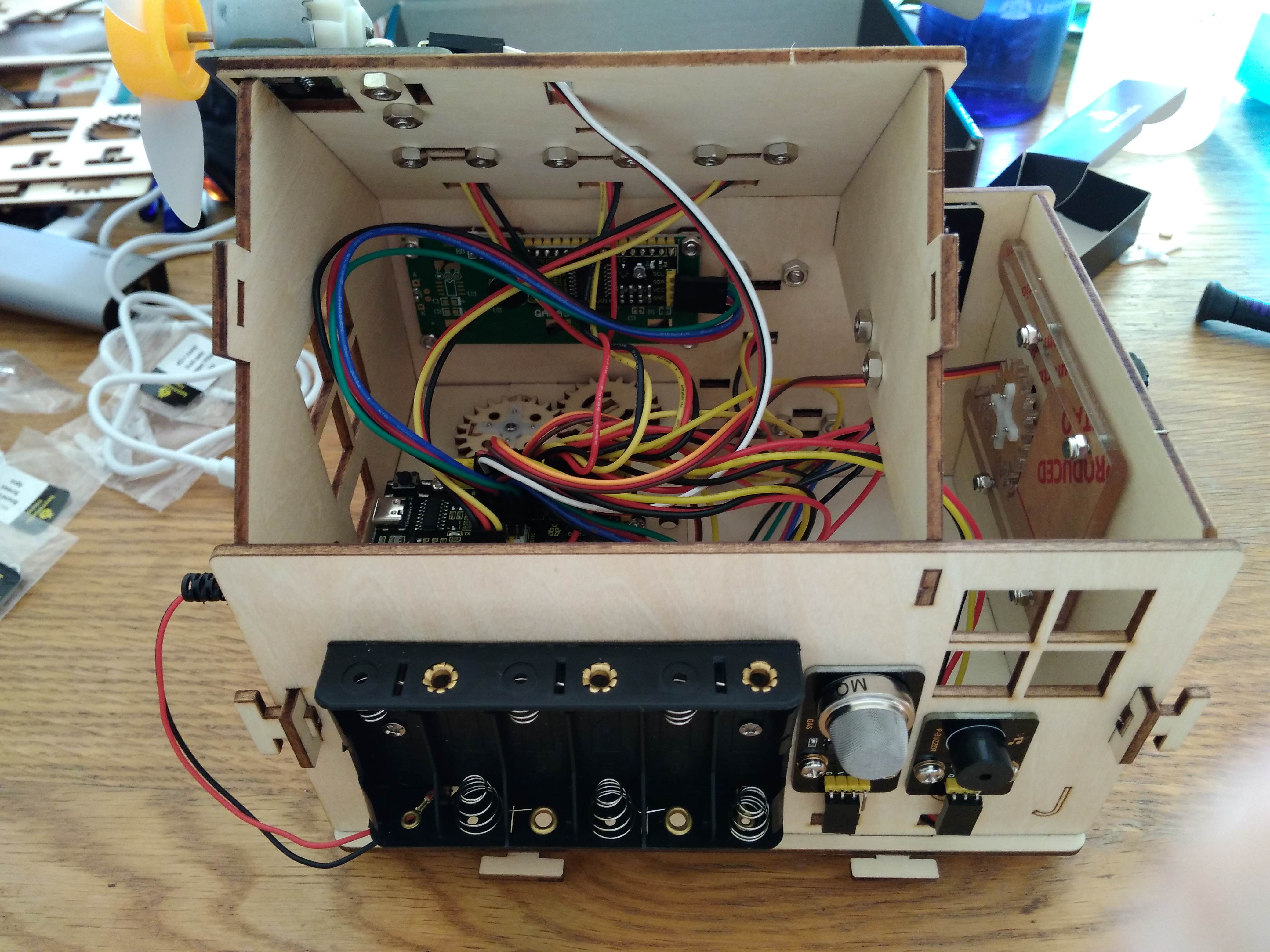
It was very satisfying to see the assembled house with the wiring done!
Day 5: Making Individual Sensors Work
Keyestudio provided arduino files to make the individual sensors work. These were brilliant for learning about arduino file structures and how the sensors could interact. I did, however, find a worrying number of errors within these files - mostly that the final close-brackets at the ends of files were missing or sometimes that extra brackets were included. Occasionally there were places where you needed to input your own information (numbers associated with your white card or blue key for the RFID or your own wifi ssid and password for the last files). It wasn't hard to personalize the code, but it'd have been useful if Keyestudio had pointed out that these changes were required within the code!I made two videos of this day's work. The first video shows what the various sensors can do.
The second video shows all of the scripts once I'd fixed the errors. I also pointed out places where changes are required, and highlighted aspects which might be tricky.
This "day" actually took more than a day because of the amount of troubleshooting required.
-The most frustrating troubleshooting involved the window powered by the gear and servo. The user manual shows that the window should be shut initially. If you do this, the window never moves, however, because the code tells the window to shut even more (the gear immediately hits the panel and gets stuck). Instead, make sure the window is initially open!
-Seemingly separate sensors sometimes affected each other. I had originally wired the RFID backwards. This meant neither the FRID nor the LCD worked? The LCD just showed solid rectangles until fixing the RFID connection.
-My own fault, I'd wired the LCD wires backwards as well. Unfortunately, I was getting an error about the LCD library being potentially too old to work so first assumed this was the problem. Spent a day looking for a newer library only to later notice I'd messed up the wires. After I fixed the wires, the LCD worked with no issues.
-There are a lot of wires in the same place on the ESP32 board. Originally, I'd shifted the buzzer pins down by one (nothing was going in as signal, the signal was going in as power, the power was going in as ground, and the ground went to nothing). Obviously the buzzer didn't work like this. It was hard to see the error with so many other wires around though.
A lot of these errors were my own. I'd found some errors in the code, however, so had already lost some trust in the provided code. This made it take a lot longer to troubleshoot! On the other hand, I learned a lot along the way.
Day 6: Connecting the ESP32 to WiFi
This has been the least fun aspect of the project and I have nearly given up multiple times.I started with the "wifi test" code provided with the kit. Despite putting in my wifi router's SSID and password, the wifi would not successfully connect. I spent a very long time on this website, which is definitely worth a read.
I used the "WifiScan" code provided within Arduino's File-Examples-Wifi to verify my wifi was visible, had the expected SSID, and had a relatively strong signal. The wifi still would not connect.
I gave up on connecting to the wifi for a few weeks, with one last try after my laptop did some auto-updates and re-started. Then the "wifi test" code said "WiFi Interface Ready" and "WiFi Client Started", but "Disconnected from WiFi access point" (with no reason provided). Progress but not all that helpful!
After a month of starting and stopping: FINALLY! The problem was my router. I used my mobile/cell phone as a mobile hotspot and the wifi almost immediately connected! This website shows others have also struggled to connect the ESP32's wifi to home routers. That person copied and pasted seemingly identical ssid and password credentials to solve their issue.
Other "days" required a lot of effort to work through difficulties, and I felt like I'd grown as a result. "Today" felt more like a waste of time. I finally understood why the wifi would not connect but not really WHY the wifi would not connect. Frustrating!
An after-note: even the mobile hotspot was patchy. The wifi would randomly drop out but it wasn't obvious the wifi had dropped, so I spent long amounts of time thinking I had wifi when I really didn't.
Day 7: Controlling the Smart House with Phone App
The hardest part of this task was realizing where to get the app. The instructions say to download the app from Google Play. Do not. Google Play has an "IoT keyes" app, which uses Bluetooth to connect to the arduino-based KS0085 smart house kit (which has different sensors). Instead, download the Android "keyes IoT home" app (uses wifi for the ESP32-based KS5009 kit we have) from Keyestudio's wiki tutorials.Installing this Android App was not straight-forward. You need to use "install unknown apps" as described here.
Once installed, the app is intuitive to use. Click a button to turn the sensor "on". Click the same button again to turn the sensor "off". Note: only two sensors can be "on" at the same time. If you attempt to turn on a third sensor, the app will wait until one of the first two is turned off to send any more commands.
The wiki tutorial page has 2 files associated with the app. The "App Test" code only controls the LED and fan. The "IoT Smart Home" code controls all of the sensors. A video showing our 4 year old using the Android App to control the Smart House is below.
A Final Overview!
Overall, the kit really delivered, especially for its price point. The whole family (3 years and up) enjoyed getting involved with the Smart House, and everyone learned something (using screwdriver, identifying letters, pressing buttons on app, connecting to wifi, troubleshooting skills, etc.).Pros:
1. Keyestudio's guide made constructing the house and adding the sensors extremely straight-forward.
2. All required equipment (sensors, screwdriver, etc) was provided and clearly labeled within the kit.
3. The arduino/ESP32 codes required to "run" the sensors were provided. Users can instantly use the sensors without needing to understand or write arduino code -- or as an additional level of learning, use the provided code to learn about arduino code.
4. There are plenty of fun sensors to play with, including some more unusual ones like temperature and humidity!
5. Incorporating the app was a brilliant end to this IoT house. It'd be nice to see a bit more information about how this app was created in the tutorials (software used, codes used, etc.).
Cons:
1. It is confusing to have 2 versions of this house. I bought this expecting an arduino, not an ESP32 board. Accidentally buying the ESP32 version both increased my frustration with the kit - and also taught me new skills. Overall, I'm glad I learned about the ESP32.
2. The guide doesn't clearly explain how to set up the Arduino IDE for the ESP32 board. Almost the entire kit is useless if the user can't manage this step - so this is a huge issue.
3. Some of the provided arduino/ESP32 codes have errors. A user unfamiliar with coding would not be able to fix these relatively simple errors, and therefore would miss out on much that the kit has to offer. I don't understand why Keyestudio hasn't already fixed these errors!
4. Some arduino/ESP32 files are for sensors (such as the NeoPixel) not included in this kit, which is confusing for the user - and seems like sloppy practice on Keyestudio's behalf!
5. Having 2 different apps is very confusing, especially as the instruction guide points the user to the wrong app! Each app should clearly specify which kit it is for (name it "KS5009 IoT Keyes" instead).
This would be a great Christmas present for anyone interested in sensors, arduino/ESP32 boards, or IoT. I'e already bought similar kits from Keyestudio that I'll be building and reviewing soon!
Other Articles:
Benzene QMC GalleryA gallery of images from an attempt to model the benzene ground state using a variational and diffusion monte carlo method. |
|


|
Experimental Flying GameFly around in a plane. Some physics, but mainly just playing with websockets. If you can get a friend to play at the same time, you should be able to shoot each other down. |