Review of Keyestudio's Arduino Robot Car KS0470
By Dr Jennifer Martay PE, Course Leader for Medical Engineering at Anglia Ruskin University
I am a Biomedical Engineer, interested in all things engineering. This is the fourth Keyestudio kit I've put together and I've really enjoyed the others
(Review of Smart House and
Review of Solar Tracker).
What did I think about this kit?
This robot car has many exciting features. The robot car uses infrared sensors to track a line and ultrasound sensors to object track or object avoid.
The car can also be controlled (forward, backward, rotate clockwise, rotate counterclockwise) using an infrared remote control or Bluetooth from a computer
or app downloaded onto a phone.
All that said, this is an older kit from Keyestudio, and I do not think this kit is as good as their newer kits. The build instructions sometimes
combine multiple steps into one picture, and occasionally, the steps are in the wrong order. In addition, the Arduino code frequently has errors.
Overall, the kit needs a lot of troubleshooting. This troubleshooting is relatively easy for someone with Arduino experience.
A novice Arduino user will probably not be able to build and use the kit.
I suggest not buying this kit (KS0470). Instead buy a newer version of a similar kit,
such as KS4034.
For more details, watch the video below and/or keep reading!
First Impressions
The box comes full of components. My first impression is that this kit has fewer sensors than newer kits - although also has a new shield which looks interesting. A booklet with brief build instructions is included. More detailed build and use instructions (including Arduino code) are available online.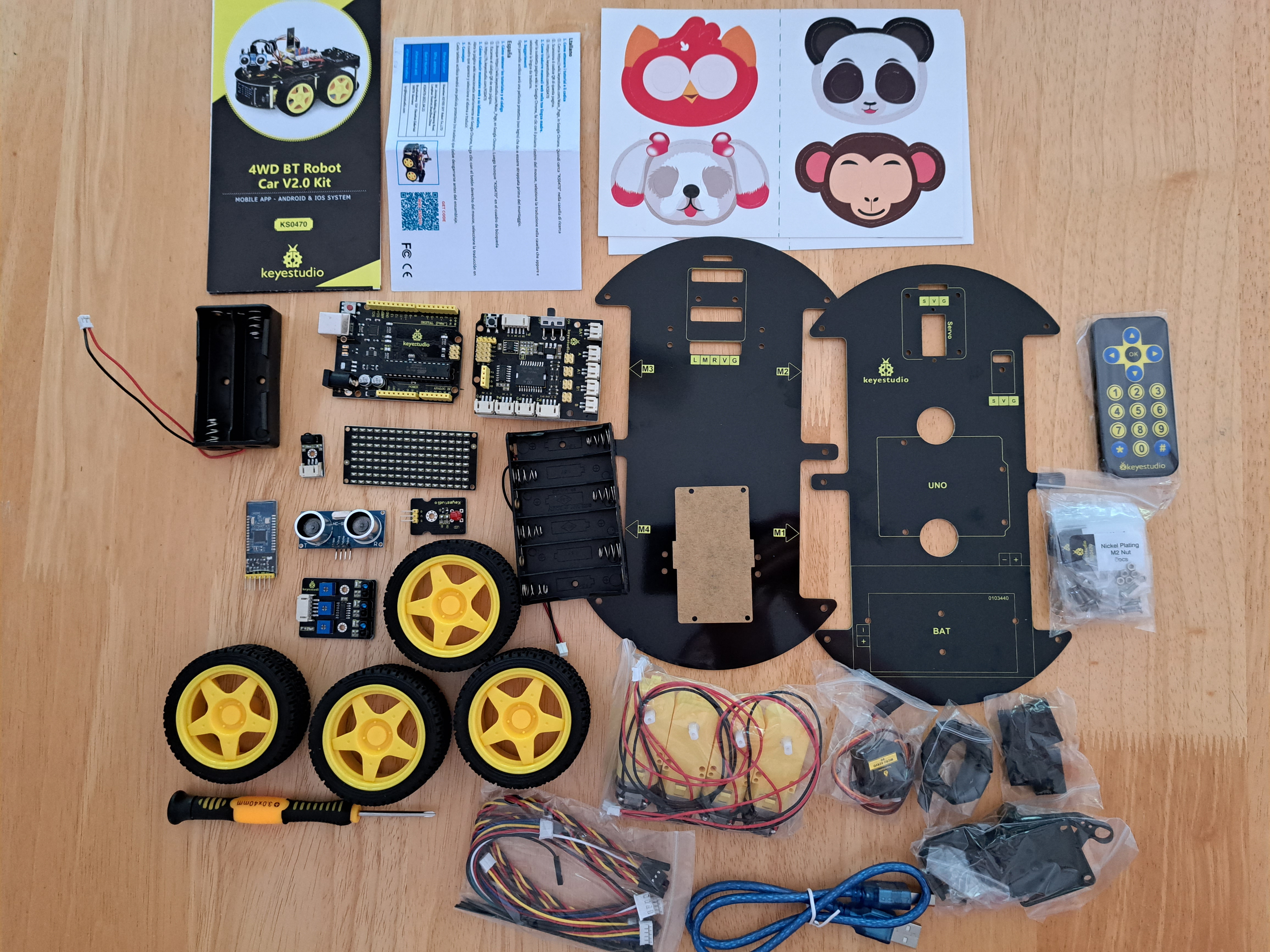
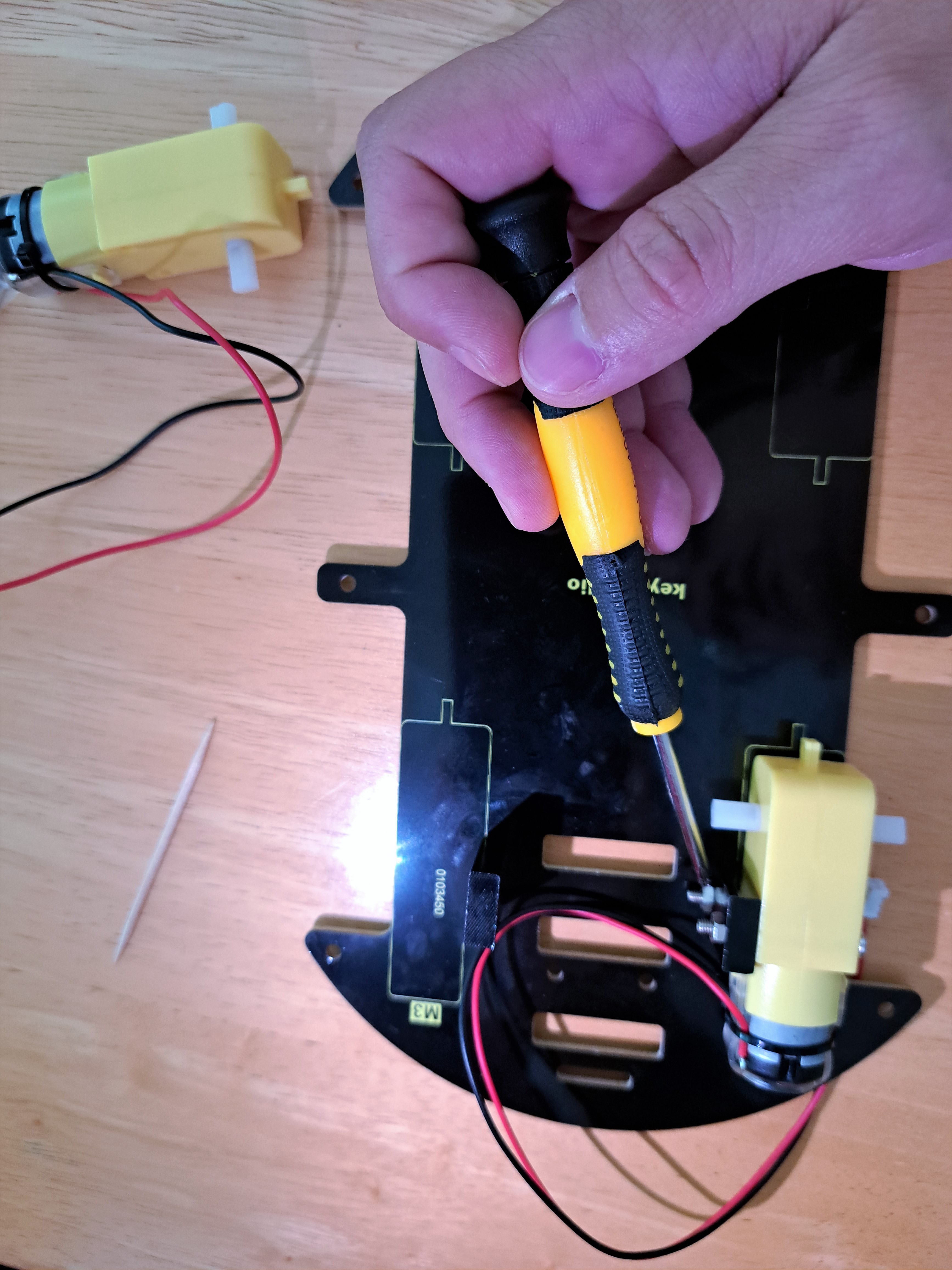
Step 1: Building the Robot Car
Generally, Keyestudio provides both written instructions and pictures of how to put together their kits. This kit only has pictures (no instructions), and sometimes the pictures show the steps in the wrong order. For example, the picture below shows screwing the gray support onto the black platform and then screwing the yellow motor onto the gray support. This is physically impossible. There isn't enough space between the bottom screw and black platform for the screw/nut on the yellow motor to turn (see second picture in the pair). It is easy to unbuild and rebuild this step, but this error makes the user lose trust in the rest of the kit.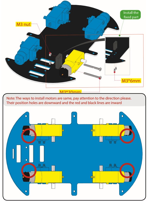
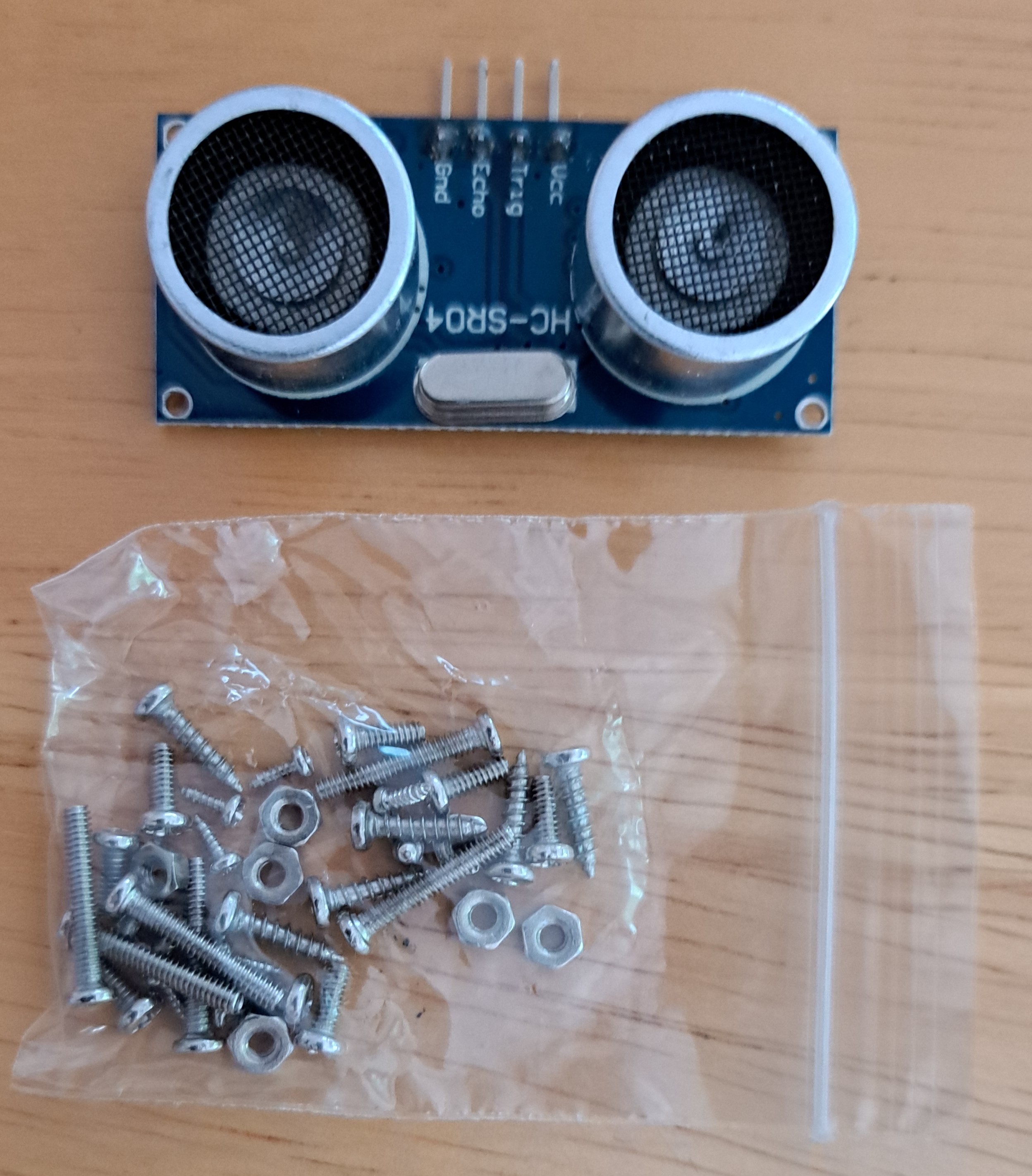
Similar to the Solar Tracking Kit, the hardest part of this build is sorting the bag of mixed, incredibly tiny screws and nuts. Sorting these into piles takes forever, and many of them fall onto the floor in the process. Luckily, there are plenty of spares (although I'm not sure why!)
Another tricky part of the build is setting the servo's initial angle to 90°. The manual explains how to use the servo many, many pages later, but the user does not know to look ahead for this information. A picture of the required wiring would greatly benefit any users not already familiar with Arduino. Code that will set the servo to 90° is provided below.
#include < Servo.h>

  void setup()
  {
    myservo.attach(10);  // servo is on pin 10
    myservo.write(90); //set servo to 90 degrees
  }

  void loop()
  {//empty for now because only want to set servo to the one position
  }
Step 2: Wiring the Robot Car
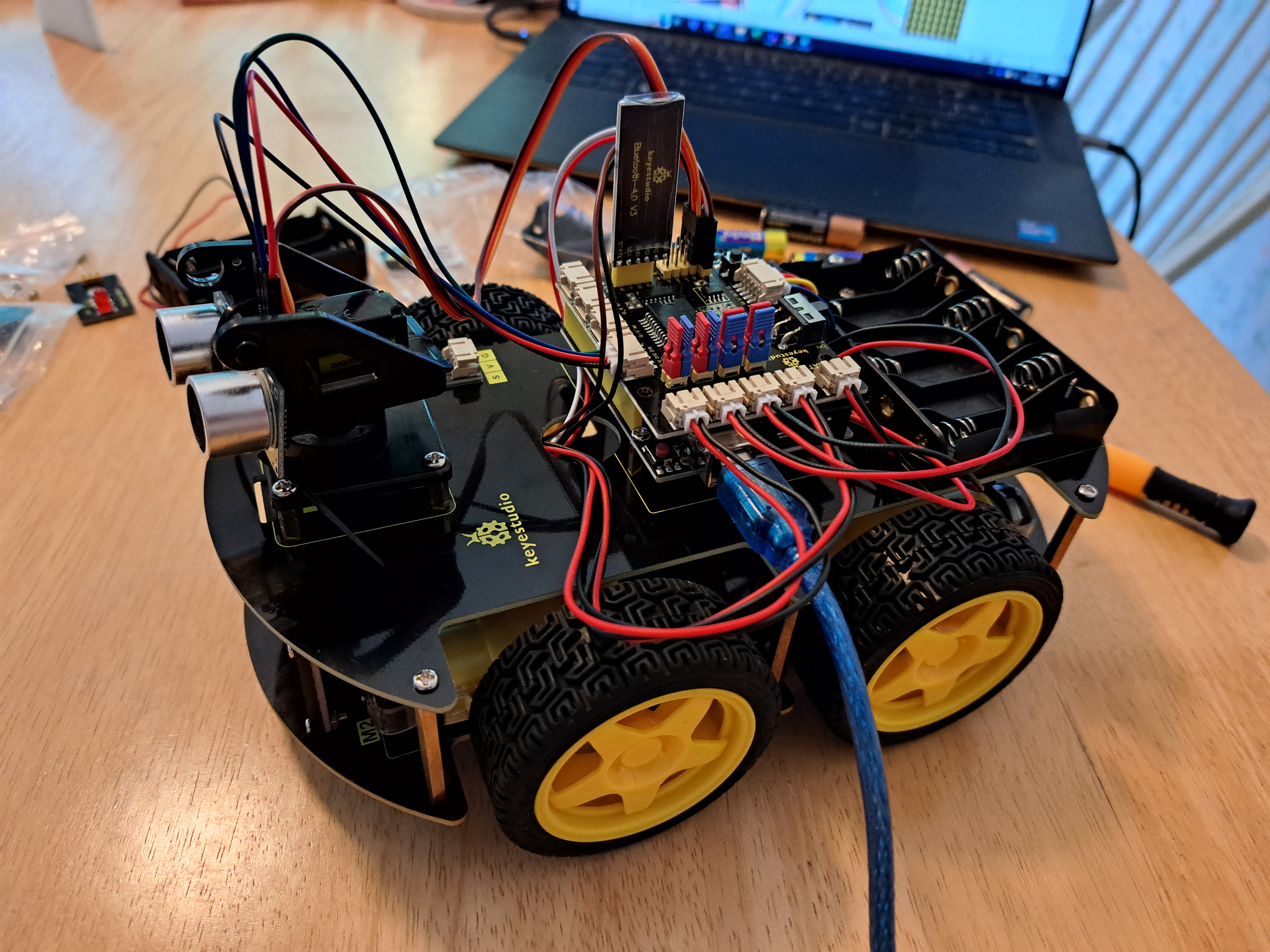
The online instructions show how to wire the various components. The explanations are clear - but doing the wiring, especially for the components on the bottom platform, is sometimes difficult.The completed robot car is shown below. The kit also includes wraps to tidy/group the wires together, but I did not use them.
Step 3: Using the Robot Car
Using the robot car is not as easy as I had hoped.The first obstacle is uploading the Arduino code onto the Arduino. The code will not upload if the Bluetooth sensor is in. This obstacle is very easy to overcome - if you know what is wrong! If the user is following along in the manual, however, the manual has already put the Bluetooth sensor into the car and never said to remove the Bluetooth sensor -- which means the Arduino code will not upload and the user is stuck and frustrated! Take the Bluetooth sensor out of the car before uploading Arduino scripts to the Arduino! If the code involves the Bluetooth sensor, you can put the Bluetooth sensor back into the car after uploading the Arduino code.
The manual introduces sensors one at a time, with separate codes for each sensor. This gentle introduction is useful for anyone new to electronics. Introducing each sensor individually is also necessary - as almost each code requires changes before it will work. Troubleshooting all of these changes at once is difficult, even for experienced Arduino users. People without Arduino experience will likely not be able to troubleshoot this many required changes and will not be able to use the robot car.
The provided Arduino code needs the following changes to work:
Code involving the Single LED Light:
int LED_pin = 3; //(not 9 or 11)
Code involving the Infrared Sensor:
int RECV_PIN = 14; //(not 3)
Code involving the LED Board on the Front of the Car:
unsigned char smile[] = {0x00, 0x30, 0x08, 0x04, 0x02, 0x02, 0x02, 0x02, 0x02, 0x02, 0x02, 0x02, 0x04, 0x08, 0x30, 0x00};
unsigned char right[] = {0x00,0x00,0x00,0x00,0x00,0x00,0x44,0x28,0x10,0x44,0x28,0x10,0x44,0x28,0x10,0x00}; //this originally said left
unsigned char left[] = {0x00,0x10,0x28,0x44,0x10,0x28,0x44,0x10,0x28,0x44,0x00,0x00,0x00,0x00,0x00,0x00}; //this originally said right
unsigned char STOP01[] = {0x00, 0x70, 0x50, 0x7c, 0x00, 0x7c, 0x44, 0x7c, 0x00, 0x40, 0x7c, 0x40, 0x00, 0x5c, 0x54, 0x74}; //correctly says STOP
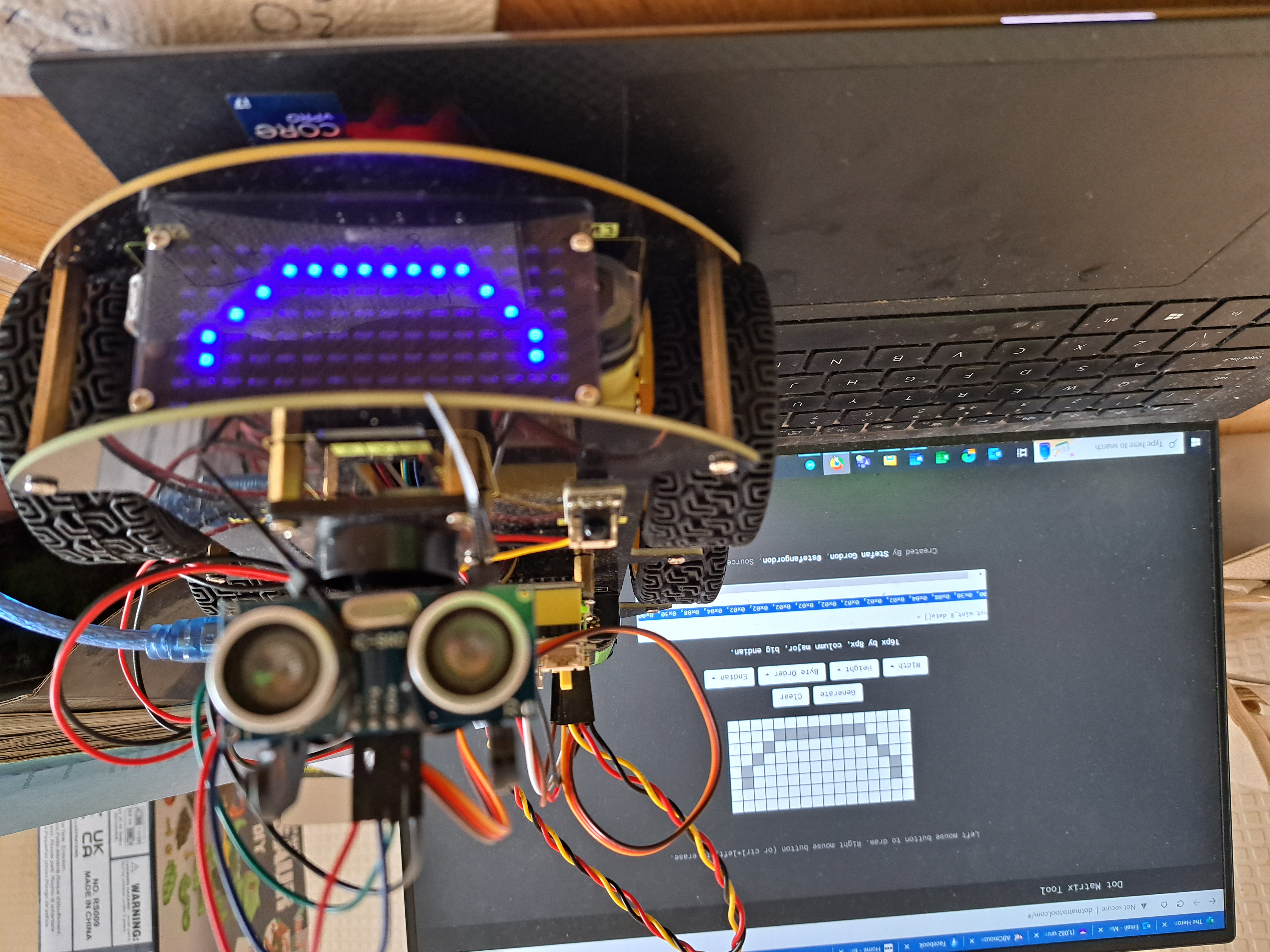
I made the smile and STOP code above using this dotmatrix tool - which is very cool although requires mirror writing! Look how happy the car is!
Code involving the Motors to drive the Car Wheels:
#define MR_PWM 9 //not 6
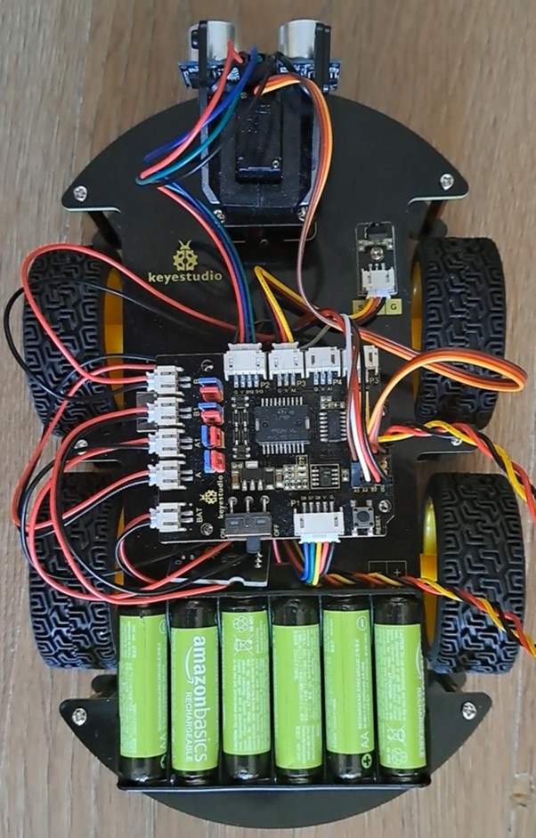
The manual shows two different configurations of the red and blue jumper caps (all in a line or as in the picture below). The different configurations make the car move in different ways. If you want to use the provided Arduino code, you need to use the configuration shown below.
Code involving Line Tracking:
int L_pin = 6; //(not 11)
I spent a very long time troubleshooting the Line Tracking. Line Tracking uses 3 infrared sensors on the bottom of the car. Each sensor determines whether it "sees" light or dark. If the middle sensor "sees" dark, the car goes forward. If the right or left sensor "sees" dark, the car rotates in the direction of the sensor which sees "dark". The sensitivity of the sensors can be adjusted and makes a large difference in how well Line Tracking works. I suggest making the middle sensor very sensitive, and the right and left sensors less sensitive.
I also suggest having the sensors check for the line more often by shortening the delay between data collections from 2000 (2s) to 500 (0.5s). Otherwise the car drives over the line without realizing it.
With these changes, the Line Tracking is moderately successful. The car is jumpy and occasionally needs little pushes to find the line again. It is clear, however, that the Line Tracking principle is working. Line Tracking might be more successful if the 3 sensors were placed further apart - or if the car made more subtle changes in direction.
Code involving Object Tracking and Avoidance:
No code changes required! Object Tracking and Avoidance are major features of this kit, though, so a review without mentioning them would be incomplete!
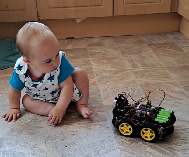
The car uses ultrasound sensors to maintain a certain distance between itself and an object (Object Tracking) or to avoid running into objects (Object Avoidance). For Object Avoidance, when the car comes within a certain, specifiable distance of an object, the servo rotates the ultrasound sensors 90° to the left and to the right, and the ultrasound sensors measure how far the nearest object is in both directions. The car then moves towards the further away object.
This is one of the most satisfying parts of the project. I let the car drive (Object Avoidance) around our kitchen, with our 10-month old in the middle of the kitchen. Luckily for the car, the baby took a while to decide to go after the car - and the baby never caught the car!
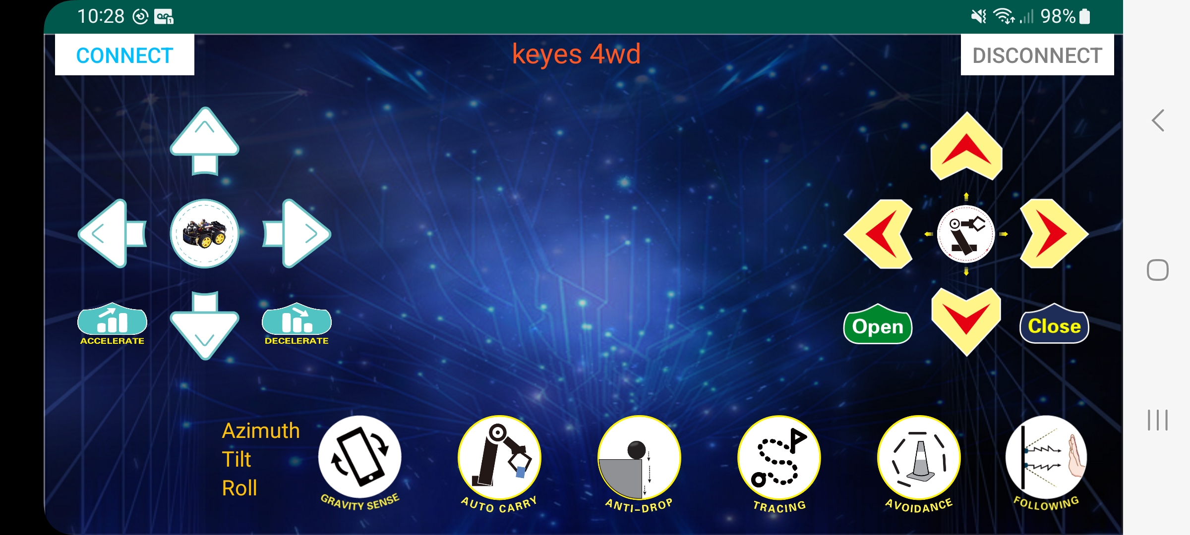
Using the Keyestudio App:
To use the downloaded Keyes 4wd App, you need to make the following changes on your phone:
-Open Settings on phone
-Find 'Keyes 4wd' Robot App in Settings
-Click on Permission Options of the App
-Enable Positioning and Nearby Devices permissions within the App.
Using the Keyestudio Robot Car:
After making all of these changes, the car does work, and both I and my children enjoyed playing with it. The car is robust and survived multiple crashes into walls and other household objects. As seen in this video, one of the wheels frequently fell off. The car kept going despite the missing wheel, which actually increased the fun-factor for my children!
As for the App, the arrows and Gravity Sense function work well and are fun to use. Avoidance and Following work most of the time. I could not figure out what Auto Carry is. I did not try Tracing or Anti-Drop.
A Final Overview!
Things I really liked:-Driving the car, especially using the App!
-Learning principles behind (one approach to) Line Tracking, Object Tracking, and Object Avoidance.
-Thinking about why Line Tracking wasn't working and trying different solutions (surface colors, line thickness, line surface, sensor sensitivity, etc).
-Involving my kids in the project - letting them drive the car and understand how the car works.
Things I suggest improving:
-Including written instructions on how to put the car together (not just pictures).
-Fixing provided Arduino code to have correct pin numbers!
-Highlighting in the manual that the Bluetooth sensor needs to be removed before uploading new Arduino code.
-Highlighting in the manual that the phone settings need to be changed to use the App.
-Adding extra space between the 3 sensors used for Line Tracking.
This is both a frustrating and fulfilling kit - both due to the amount of required troubleshooting. I learned a lot more about the robot car than I expected.... because deeply understanding the car is the only way to fix the errors and get the car to work. It is satisfying to see the car going in the end, though!
Good for an experienced user. Not for an Arduino novice!
Other Articles:
Benzene QMC GalleryA gallery of images from an attempt to model the benzene ground state using a variational and diffusion monte carlo method. |
|
|
Moon FormationA Kotlin N-Body code, and lots of animations of the collision between Earth and a hypothetical Theia that people think created the moon. |

|
Physics Algorithms BookThis is a work in progress to write a book on physics algorithms. At the moment, it is about 1/3 finished though, but the latest version can be downloaded for free. |