Review of Keyestudio's ESP32 Smart Farm KS0567
By Dr Jennifer Martay PE, Course Leader for Medical Engineering at Anglia Ruskin University
I am a Biomedical Engineer, interested in all things engineering and building up my electronics skills and understanding of the Internet
of Things. I previously built Keyestudio's Smart House, and that kit
remains one of my favorite kits. Therefore, I was very excited to build this Smart Farm!
What do I think about this kit?
This kit is great! The build is straight-forward, although I did make a few mistakes along the way (the instruction manual is
clear - I just used the wrong wires!). The Smart Farm is packed with sensors, which can be controlled by either Scratch (a
drag-and-drop programming language good for younger users) or by Arduino IDE. I used Arduino. Each sensor is introduced
individually before tying multiple sensors together (for example, turning on a fan if air temperature gets too high).
This kit can be enjoyed by anyone interested in electronics - whether this is their 1st or 100th kit. The Smart Farm is
visionally-appealing with loads of small touches (farmer, sheep, picket fence, hidden battery pack, etc) and learning
opportunities.
For more details, watch the video below and/or keep reading!
First Impressions
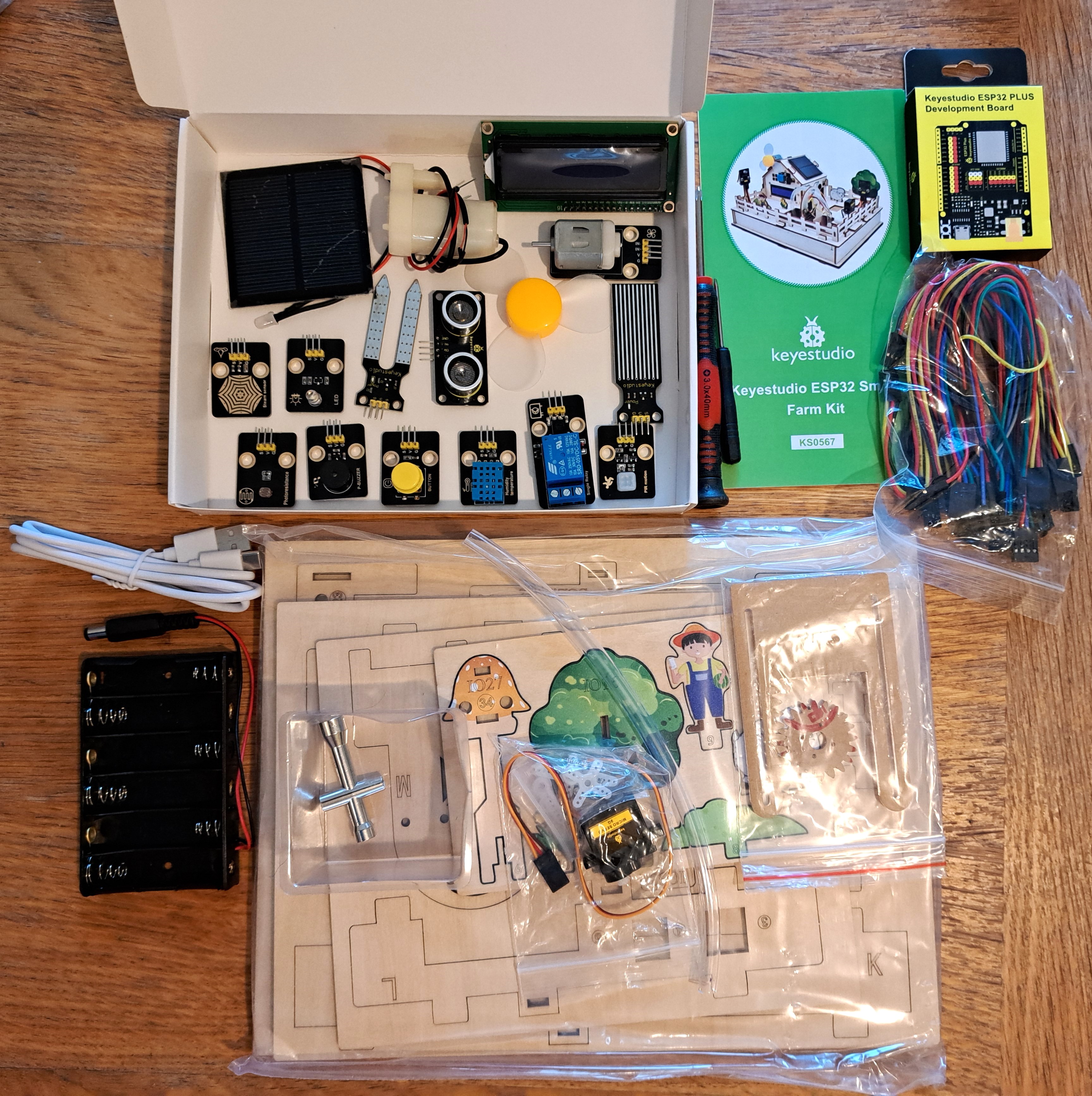
This kit gives equal attention to the visual appeal and to the sensors - which I personally really like! There are loads of laser-cut wood pieces to make the farm and surrounding features. There are also loads of sensors: temperature/humidity, PIR, soil moisture content, water level, LEDs, solar panel - and a water pump and ESP32. There is so much to this kit! I like how everything ties into the farm theme. Also, HURRAY for AA batteries!Links to instructions for building and using the Smart Farm are also provided.
Step 1: Assembling and Wiring the Smart Farm
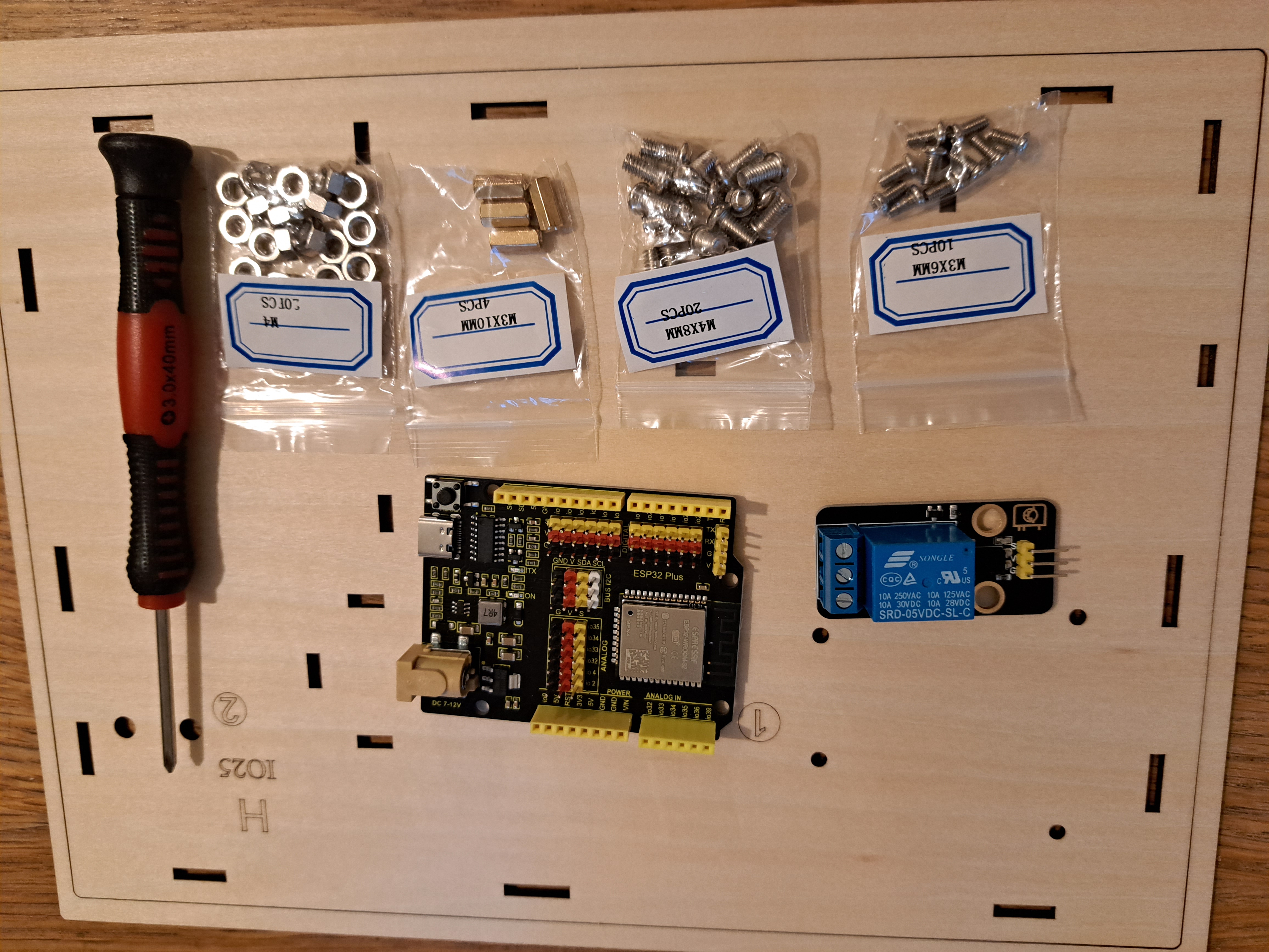
Each step of building the Smart Farm is explained and shown in a pdf instruction manual downloaded from Keyestudio's wiki website. The required parts for each step are first listed. Then the relative positions of parts are shown in figures. I like to lay out the parts as in the figures and then follow the manual step-by-step. Examples showing part of building the bottom of the Smart Farm are shown below.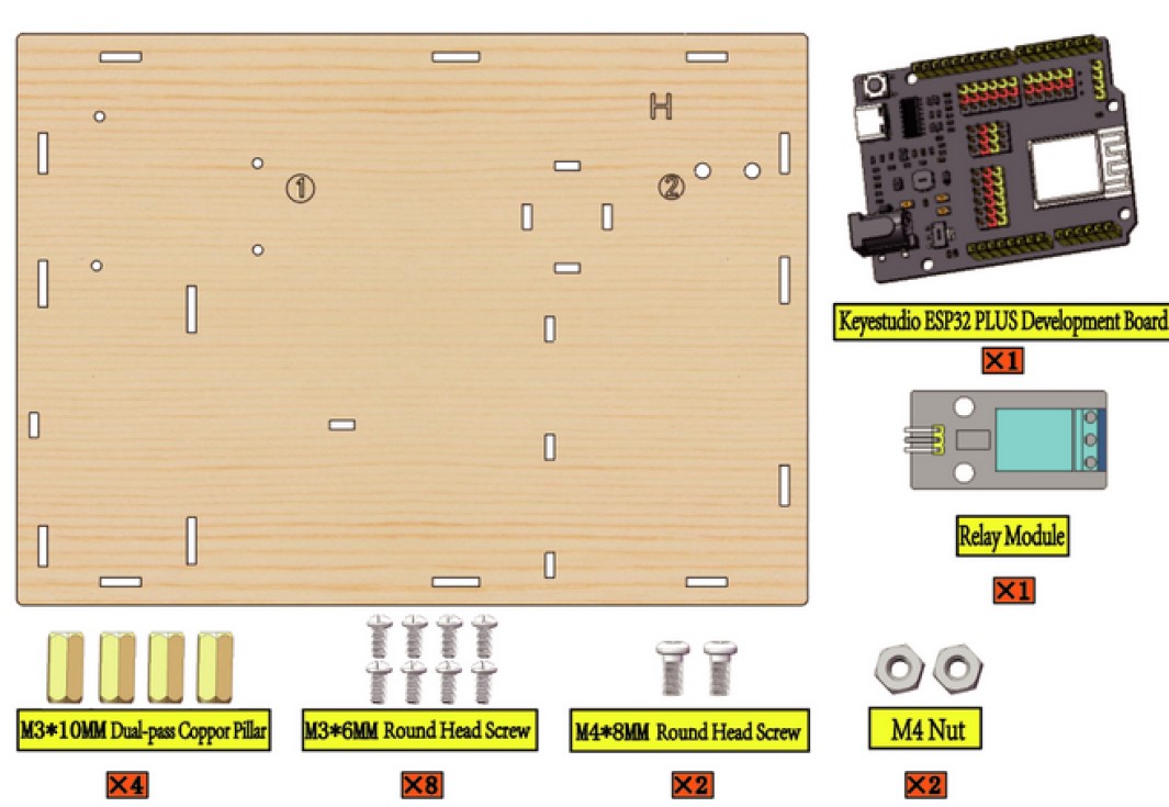
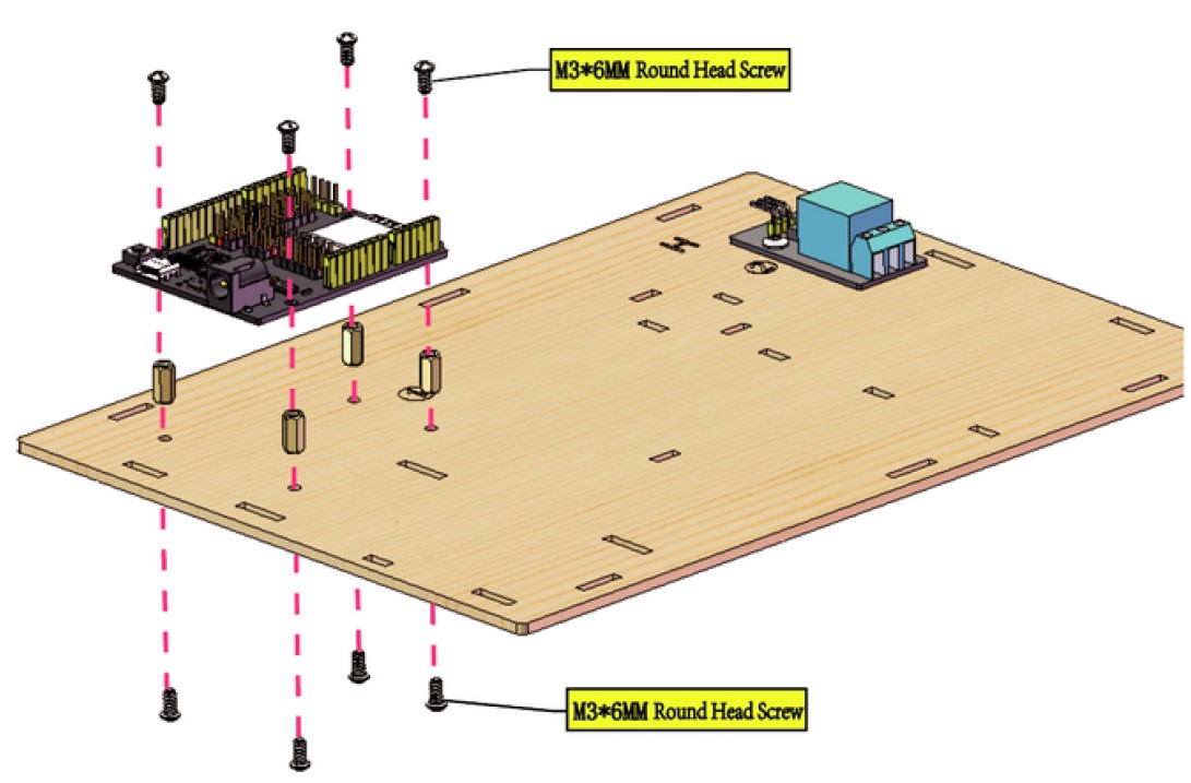
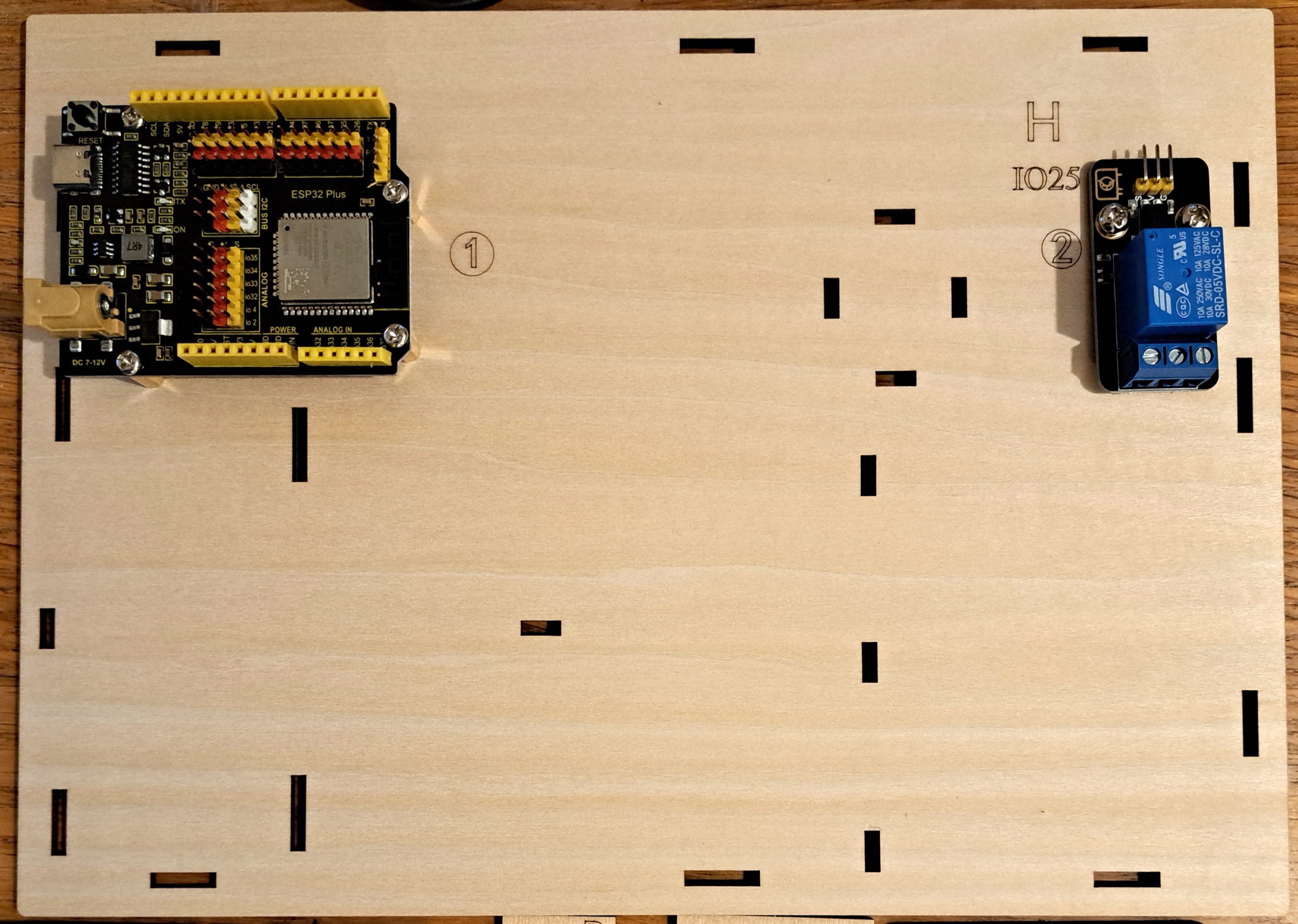
Underground Layer of Smart Farm
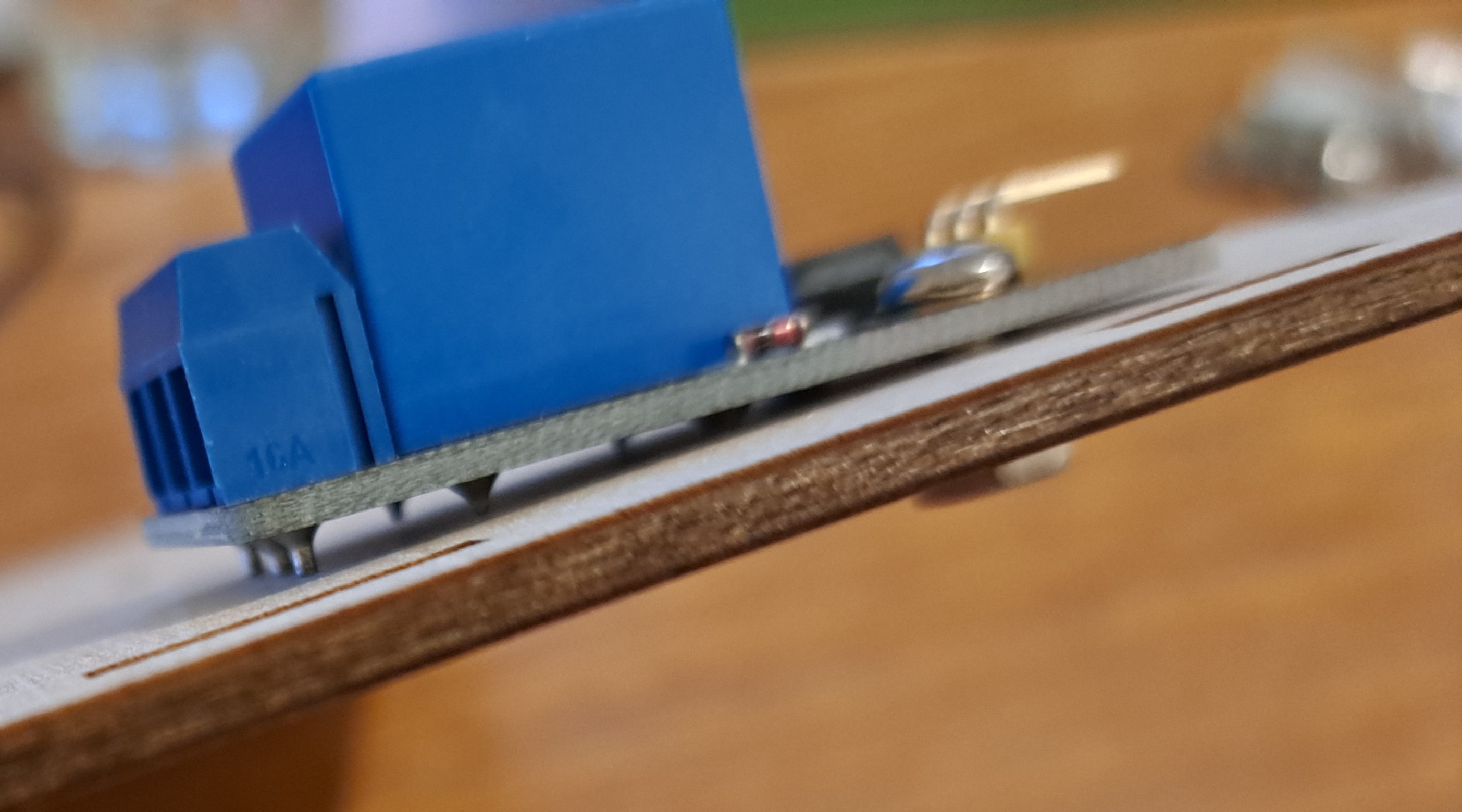
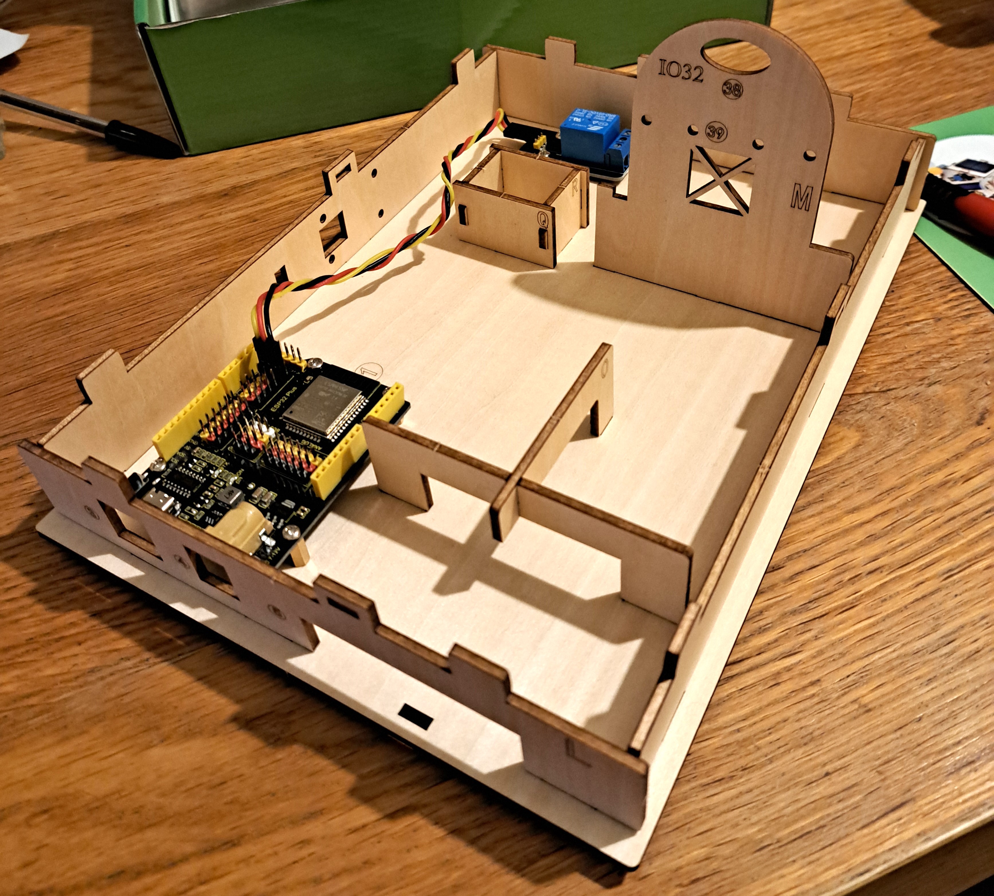
The relay, ESP32, and wooden supports for other parts of the Smart Farm are added in this step. Note, the relay's soldering cone is relatively tall so the relay is not level on the bottom base (Part H); the unlevel relay does not cause any problems. The ESP32 is cleverly positioned on this bottom level, hidden under the eventual Farm, yet with holes in the side supports so that the ESP32 power and USB ports can still be accessed. The relay and ESP32 are wired together. I twisted the triplet wires to make it obvious these three wires go together. A rectangle feeding box is created. The support for the watering station is added. Crossed supports are also added near the ESP32 to later hold the battery pack in place. The wooden supports are pressed into place, sometimes also using wooden T pieces. These wooden supports are easy to put in and take out (as I needed to do when I made various errors during the build!). The completed Bottom of the Smart Farm is shown below.
Ground Layer of Smart Farm
The main feature of the Ground Level is the sliding door of the feeding area. The sliding door is controlled via a servo, which needs to initially be set to 180° and then positioned so that the sliding door is initially *closed*. (Note, the later separate instructions for the servo say to set the servo to 0° initially but it should be 180°!)
Farmhouse
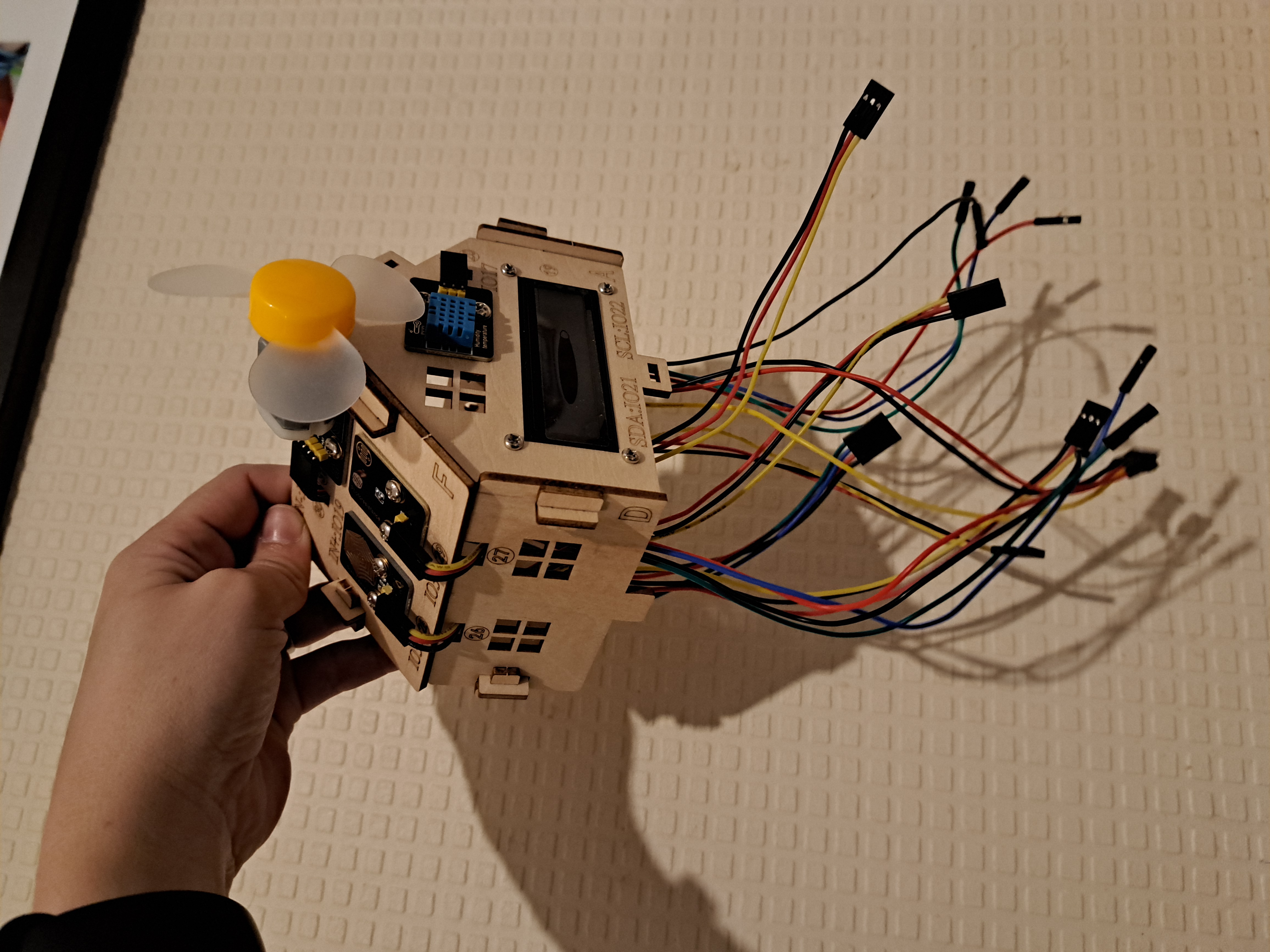
Three of the 4 walls of the Farmhouse have sensors. One wall has an LCD screen and temperature/humidity sensor. One wall has ultrasound sensors. One wall has a button and PIR sensor. The final wall has 2 windows, presumably for ventilation. The 4 walls are assembled into a house shape, and the required wire is attached to each sensor. The instruction manual clearly says which wire (3 or 4 wires, divided or connected, 15cm or 20cm or 25cm length) to use for each sensor. One of the 2 roof panels is then prepared with a steam sensor, photoresistor, and fan. Wires are also attached to these sensors and the roof panel is added to the house. At this point, the Farmhouse looks a bit like a jellyfish!
Assembling the Smart Farm
The Farmhouse is added on top of the Ground Layer of the Smart Farm. The wires are pulled through the Ground Layer and attached to the ESP32 in the required locations. Wiring is very easy because the instruction manual states and shows the port required for each wire. Using (mostly) triplet wires also means there is really only 1 wire, rather than 3 wires, to place. The order of wiring the ESP32 is also well-thought-through. Ports are wired sequentially so previously-placed wires can be used to guide future wires into position. I twisted each triplet of wires to make it easier to see each grouping.
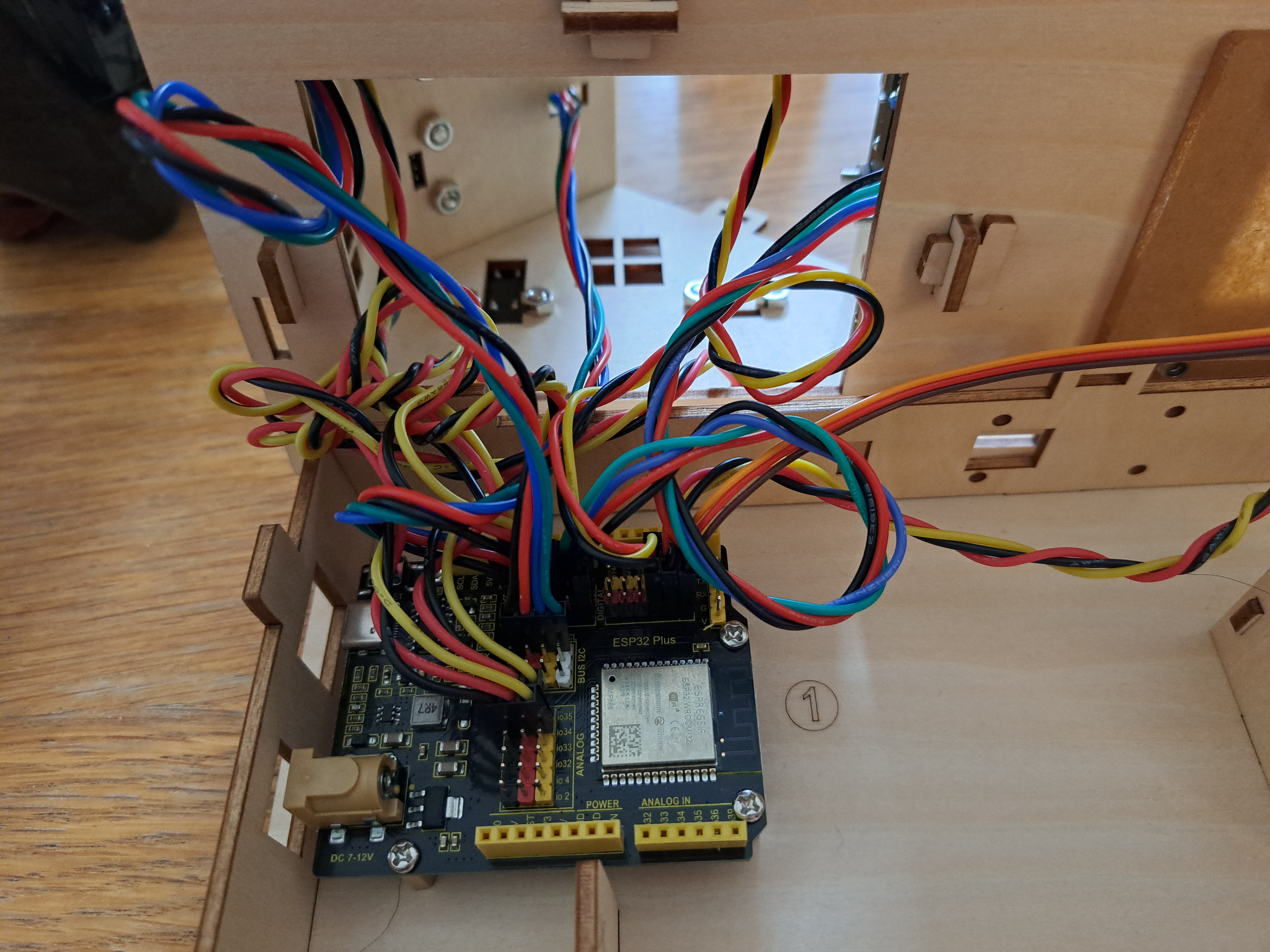
Be aware that this step also places wires for sensors not yet added to the Smart Farm. At first, this confused me - but the Ground Layer of the Farm is added over the Underground Layer in the next step, making the ESP32 inaccessible. The wires have to be added now, even if the structures the sensors will be attached to have not been added yet.
The Ground Layer is placed over the Underground Layer. Then two plastic tubs are placed, with a water level sensor in one tub and a soil moisture sensor in the other tub. This is when I realized I'd used the wrong wires for some of the sensors - because these two sensors' wires could not reach from the sensors to the ESP32. I disassembled the Smart Farm and changed multiple wires so that the shortest wires went to the closest sensors (Smarthouse) and the longest wires went to the furthest sensors (buzzer, water/soil). Again, the instructions clearly said which wires to use for these sensors - I just hadn't followed the instructions! Lesson learned. I can confirm that it is easy to disassemble and reassemble the Smart Farm, though! A water pump and tube are also added to the plastic tubs.
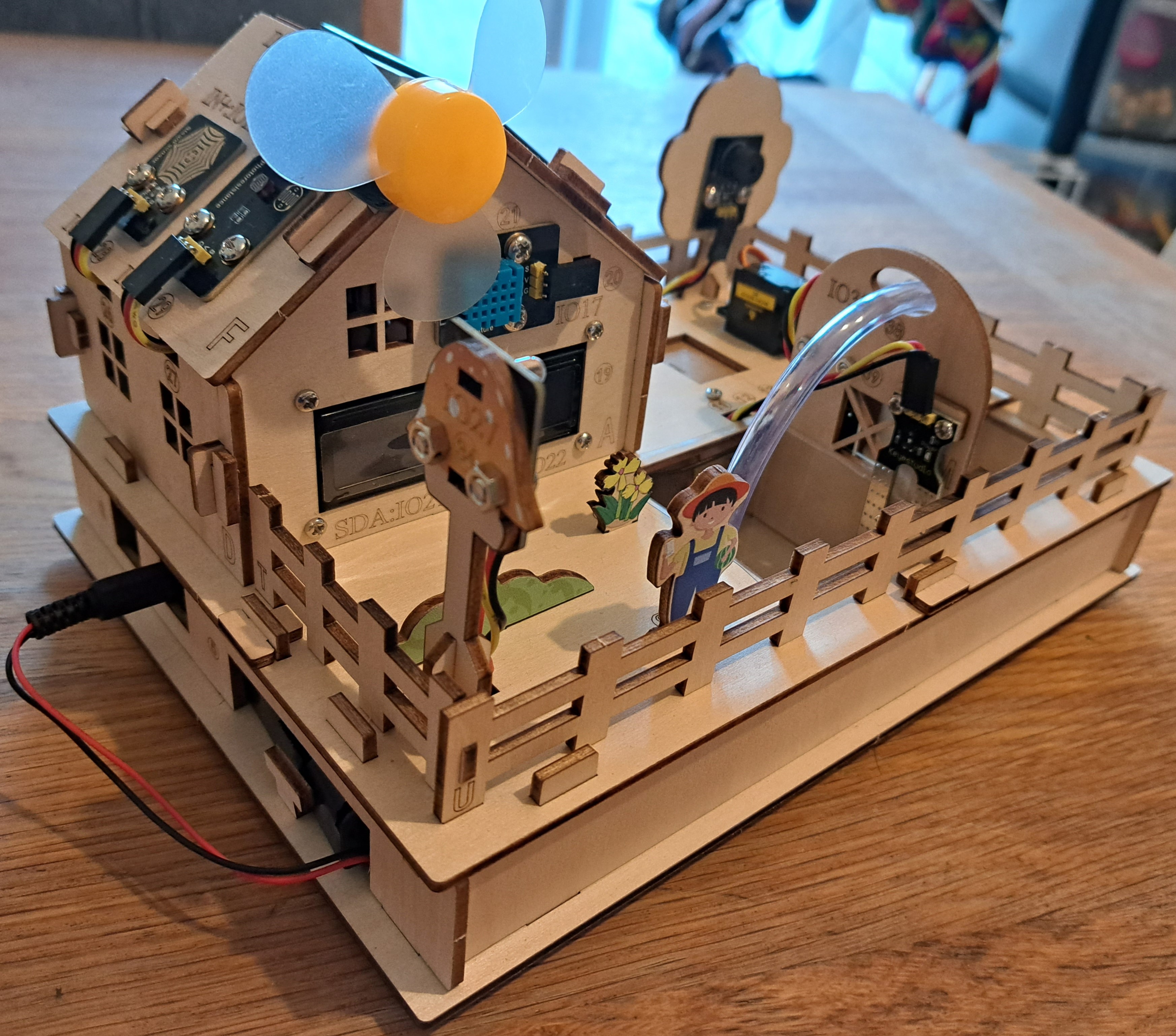
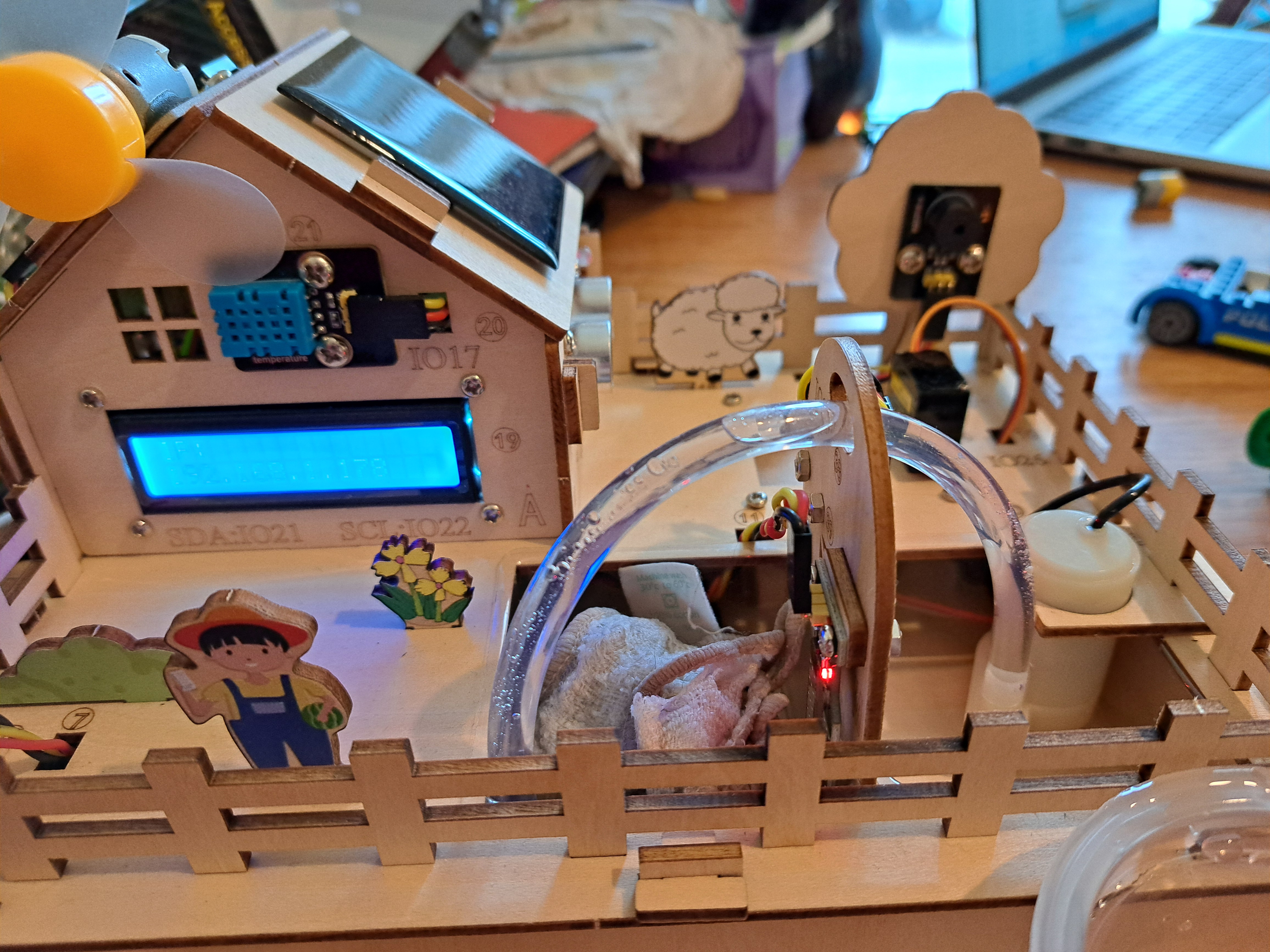
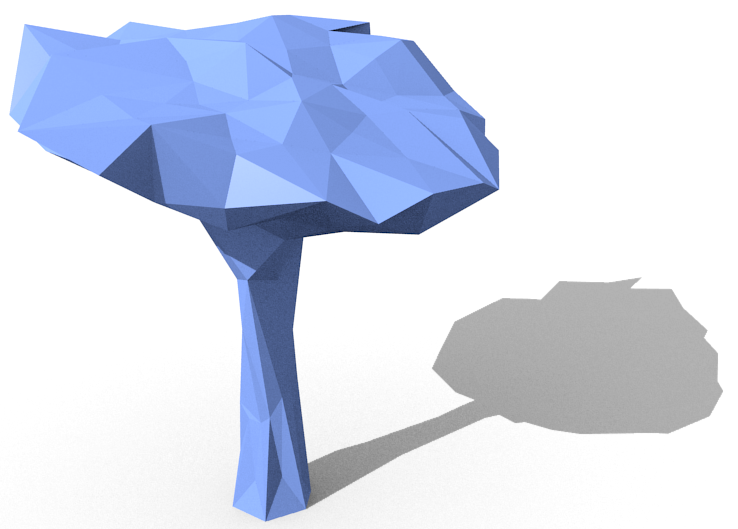
Next, a picket fence is added - as well as a tree with a buzzer and a mushroom (I think??) with an LED. A farmer, sheep, flower, and grass complete the scenery. Finally, a solar panel which powers a small LED is added to the remaining Smarthouse roof panel. The LED and roof panel are fitted to the Smarthouse. A final addition, which I think is genius, is hiding the battery pack in a slot into the Underground Layer! Congratulations - the Smart Farm is assembled and wired!
Step 2: Using the Sensors
Onto using the sensors!The Smart Farm can be controlled using either Arduino or Scratch code. Both sets of code are provided in well-organized folders on the wiki website. I used the Arduino code for this kit. (I have used Scratch for other kits and agree that Scratch is very user-friendly!)
First things first: the ESP32 is not the same as an Arduino uno. I had an incredibly difficult time figuring out how to get the Arduino IDE to talk to the ESP32 with the Smart House. Keyestudio has made HUGE improvements with the Smart Farm documentation! Every step of setting the correct board within Arduino IDE and using the ESP32 is explained. I really cannot overestimate how much of an improvement this is!
Back to the sensors/topics, though! Each of the topics below has its own explanation pdf. Each pdf shows the highlighted sensor(s), explains how the sensor(s) works, and shows pictures of the code used to control the sensor(s). Each topic also has a separate folder with .ino files of the actual codes which can be uploaded into Arduino IDE. It would be slightly more user-friendly to re-organize the Project folder so that each topic has its own folder with the explanation pdf and relevant codes all together in the same place.
Lighting: Introduces LED and button. LED blinks and slowly fades in/out. Button controls LED being on/off (including locking on/off condition when button not actively being pressed).
Light control: LED and photoresistor. LED comes on when photoresistor senses low light. "Photocell" misspelled in code but without any effect.
Alarm: PIR sensor (senses changes in heat to detect people/animals/etc), buzzer (different tones caused by different vibration frequencies), and LED. Buzzer sounds and separate LED comes on when PIR senses someone is present (also, confusingly, red LED on PIR sensor goes OFF when PIR senses someone is present). File named "3.3Buzzer-Tone.ino.ino" needs to be renamed "3.3Buzzer-Tone.ino".
Rain detection: Steam sensor and buzzer. Buzzer sounds when moisture is detected on steam sensor.
Solar power: Solar panel, small LED. Solar panel converts solar energy into electrical energy to power small, multicoloured LED (not the LED on the mushroom tree).
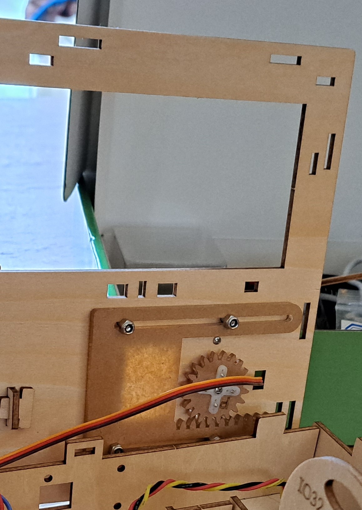
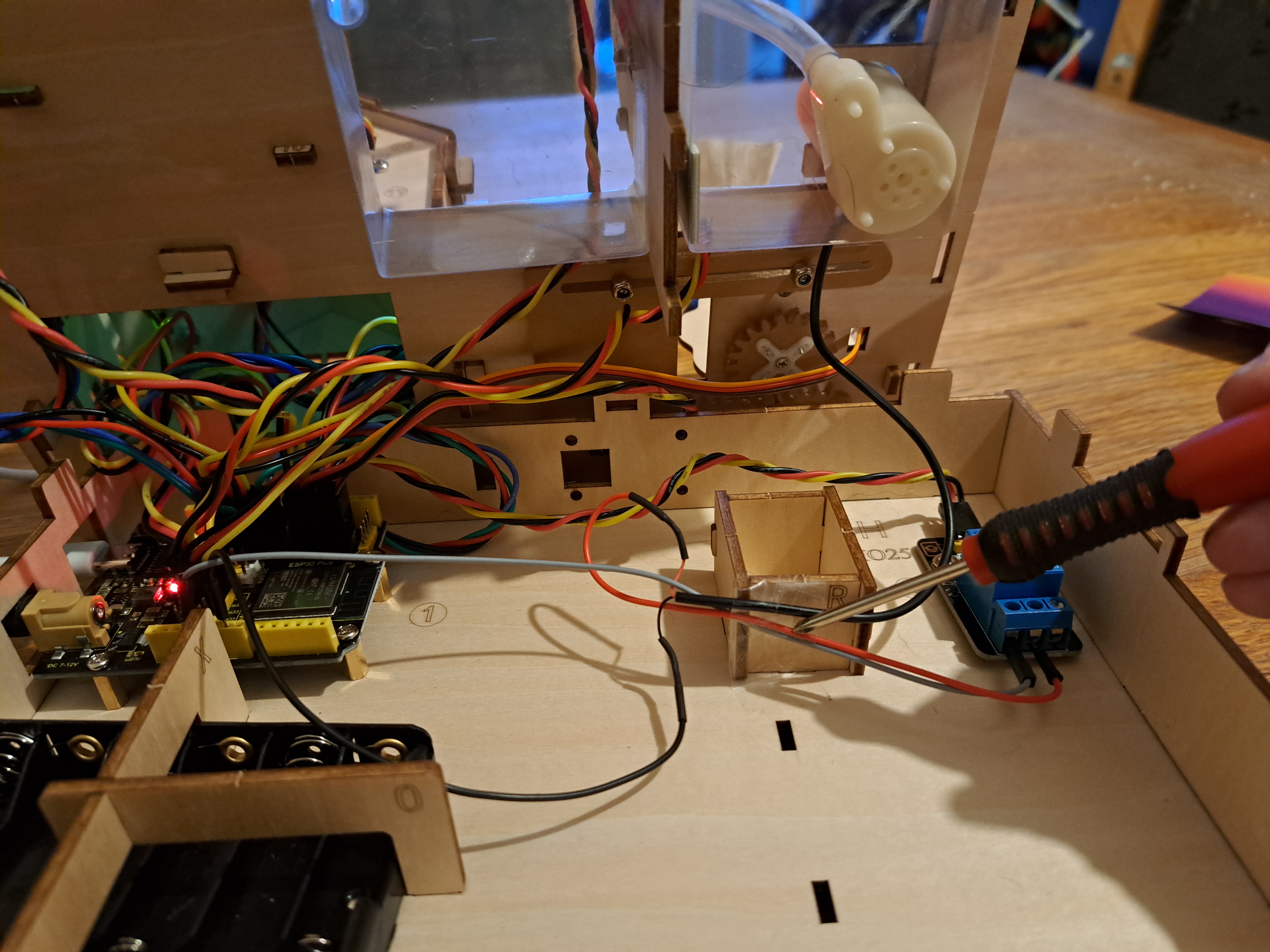
Smart feeding: Ultrasound sensors and servo. Servo opens feeding box when ultrasound sensors detect object in feeding area - and servo closes feeding box if no object detected in feeding area. Note: tutorial says to initially set servo to 0°, but this should be 180° as stated in Assembly document. Tutorial says fully opening/closing feeding box only requires 100° rotation, but I needed 150° (servo can rotate 180° so this isn't a problem). My feeding box was getting stuck in the wires for the water pump/relay. Taping these wires to the side of the feeding box (see screwdriver's location in figure below) fixed the problem and allowed the feeding box to open/close as expected.
Temperature control: Temperature and humidity sensor, fan, and LCD. Temperature and humidity sensor determine temperature and humidity, both of which are displayed on LCD screen. If temperature is above threshold amount, fan turns on (symbolizing cooling the farm's environment). Note: tutorial says fan turns on if temperature exceeds 29C but code actually uses 25C. For fun, I checked whether fan actually cools the environment; the fan either maintains or slightly increases temperature experienced by the sensor! (IoT symbolism works though!)
Soil humidity monitoring: Soil moisture sensor, LCD, and buzzer. Soil moisture sensor constantly monitors moisture level, which is displayed on LCD screen. If soil moisture levels drop below threshold, buzzer sounds alarm. Note: I assumed soil moisture sensor's "detection zone" was anywhere on flat face of sensor. If I put wet finger on just one of the flat faces, the sensor did not register moisture. Both sensors needed to be wet to get a good reading.
Water level monitoring: Water level sensor, LCD, and buzzer. Water level sensor constantly monitors water level, which is displayed on LCD screen. If water level rises above threshold height, buzzer sounds alarm.
Auto-irrigation: Water level sensor, soil moisure sensor, pump/relay, LCD, buzzer, and button. Water level and soil moisture are read and shown on LCD. If soil moisture is below threshold and water levels are above threshold, pump/relay pumps water from water pool pot into soil pot. Buzzer also sounds. Button can be pressed to stop buzzer.
WiFi control: LCD, Temperature and Humidity Sensor, Water Level Sensor, Soil Humidity Sensor, Photoresistor, Steam Sensor, LED, Fan, Servo, Water Pump. WiFi is used to display temperature, humidity, water height, steam, light, and soil humidity levels on a website. The LED, fan, feeding and watering system can be turned on/off by clicking buttons.
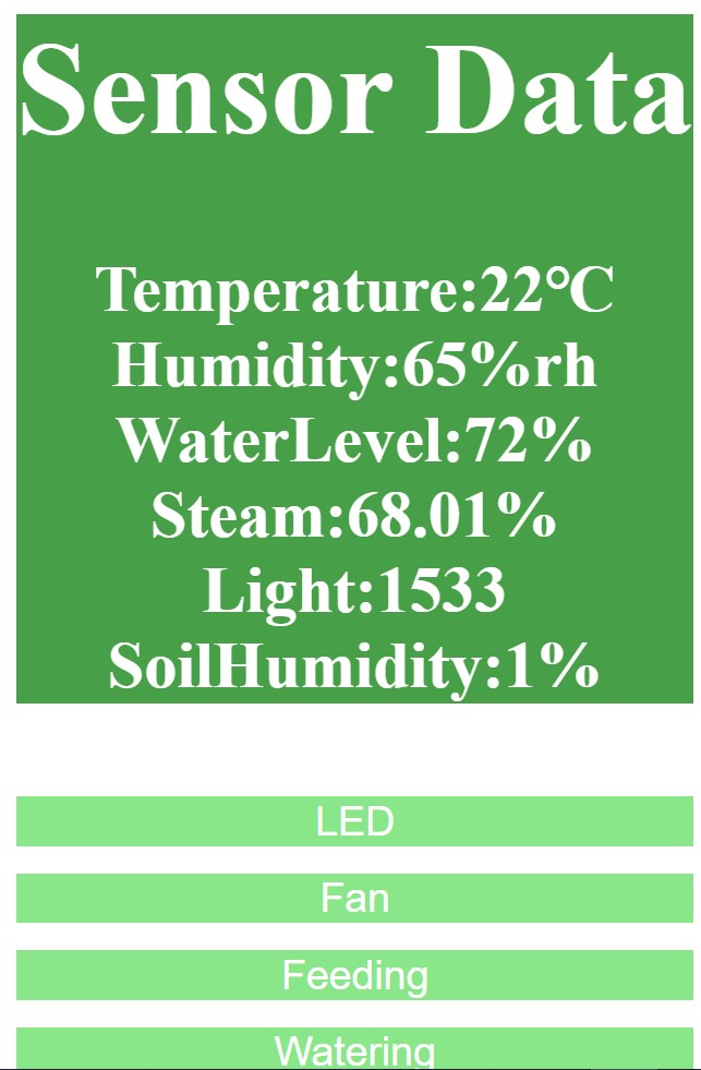
WiFi projects rarely work for me - so I was pleasantly surprised when the WiFi instantly connected in Project 11.1 (although you can't see "Connected to WiFi" and your IP address unless Serial Monitor is open BEFORE you load the .ino script!!). This IP address was NOT either of the addresses listed in "Start > Settings > Network & internet > Wi-Fi". Eventually, I found the IP address on the Serial Monitor and SmartFarm LCD. The IP address website said "Hello, World!" as expected. Project 11.2 gave me multiple errors about missing Libraries. I added AsyncTCP.h from this website, and imported Libraries for AsyncTCP, ESPAsyncTCP, and ESPAsyncWebSrv. Project 11.2 still would not load. Eventually, without any changes (!!), the code loaded and the website displayed sensor data as expected. Clicking the LED, fan, etc buttons made the LED, fan, etc come on and go out - with a large time delay! I have no idea what made the code eventually work - or whether the extra libraries were even necessary. I was just happy the code worked! The html code for making the website is also included in the code - extra learning for anyone interested!
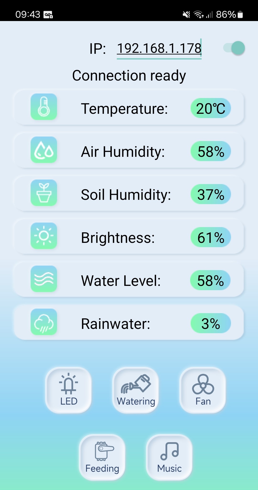
App control: LCD, Temperature and Humidity Sensor, Water Level Sensor, Soil Humidity Sensor, Photoresistor, Steam Sensor, LED, fan, servo, water pump, buzzer. The App displays temperature, air humidity, soil humidity, brightness, water level, and rainwater (steam). The LED, fan, feeding door, watering system, and music player can be turned on/off by clicking buttons.
The App was easy to locate and install. When the App downloads, it shows Keyestudio's IP address at first. I deleted the last few digits of the IP address and put in my IP address, but the App would not connect. Eventually, I realized there was an extra space before the first 1. Delete the first space! Then the App connected. The App is intuitive to use, and the toggle buttons at the bottom all worked (although I was once kicked out of the App when I tried to toggle the fan on).
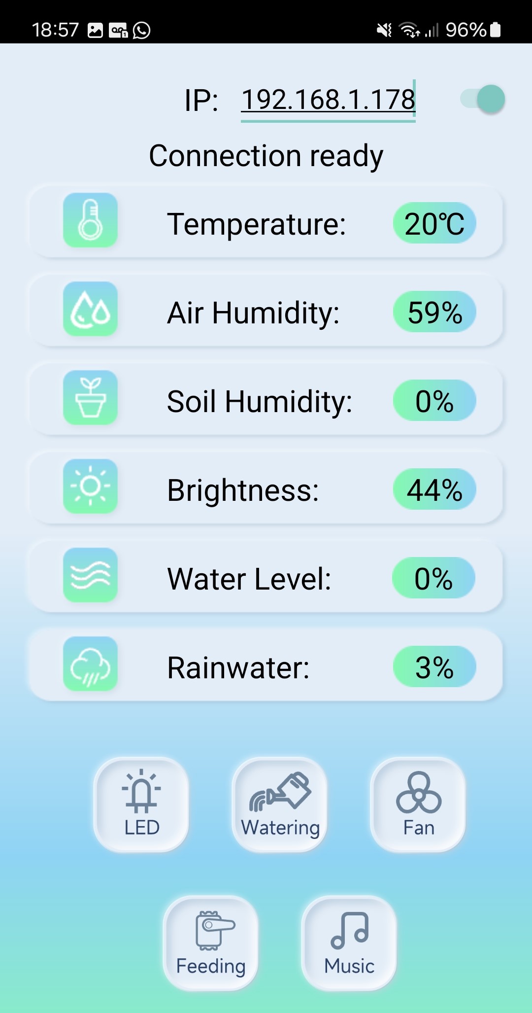
I decided to fill the water level pot and finally test out the pump. Instead of soil, I added cloth wipes on the soil side (easier to clean and dry up!). The water level showed at 100% on the App. I clicked "Watering" and the pump worked really well. It pumped all of the water over to the soil moisture pot - which was saturated but read Soil Humidity of 0% which was clearly incorrect. I closed the App and went back to Project 11.2 to see what Soil Moisture level the IP website displayed - it displayed 99% soil humidity. At that point, I tried to go back to the App to see if perhaps there was an error in the App code. The App would not connect again for me though. I tried restarting my phone, uninstalling and reinstalling the App, reconnecting >20 times - and the App just would not connect again.
I tried to use the App again the next day. The App *WOULD* connect if I put the IP address into the App *BEFORE* I uploaded the code to the ESP32. This method did not always work but did work about 50% of the time. Another improvement, the soil moisture levels were correct this time. I don't know what the difference was!
I did not try controlling the Smart Farm with the Scratch code.
A Final Overview!
Things I really liked:-The sensors, functions, and aesthetics all build really well on the farm theme!
-Some creative design aspects here - like hidden battery pack area and sliding feeding box.
-Being able to choose to use Arduino IDE or Scratch.
-Instruction manual and Arduino codes very easy to use.
Things I suggest improving:
-Make App more reliable. The App (for my Android phone at least) sometimes connected/worked but many times would not connect/work. Keyestudio is looking into this so hopefully the App will become more reliable soon (or maybe it was just my phone??)!
-Fix Tutorial to say to set servo initially to 180° rather than 0° (Instruction manual correctly says 180°).
-Add more space around the sliding feed door so the door does not get stuck on nearby wires.
-Highlight importance of using correct wires for particular sensors. Otherwise, it's easy to use the wrong wires, which then don't reach from sensors all the way to the ESP32.
This kit makes some big improvements over the Smart House - which I already loved. This Smart Farm might be my favorite Keyestudio build! The Farm looks great and is a lot of fun to put together. The wood pieces fit together easily with so many little design touches tying into the farm and IOT themes! Sensors are wired in a well thought-out order. Provided Arduino codes all work correctly, and tutorials gently guide users through each individual sensor before pulling the sensors together into IOT tasks. Something in the App seems to need fixing, but the wifi/website functions worked well. Overall, an excellent kit for builders of any ability/experience.
Other Articles:
|
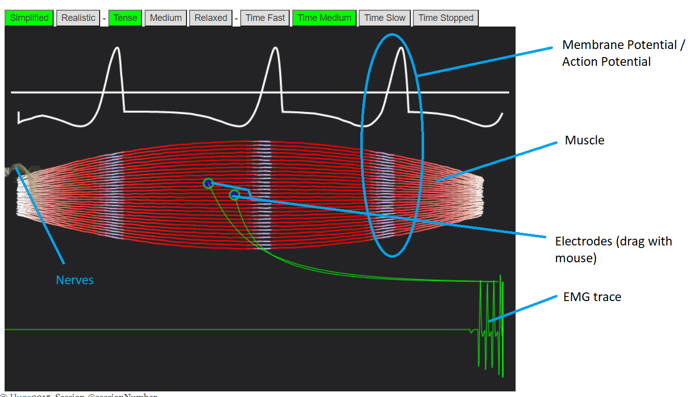
BodyWorks: Neuromuscular Activity / Muscle EMGAn interactive simulation showing how nerves travel to and down muscles, and how this gets picked up by EMG sensors. |
|
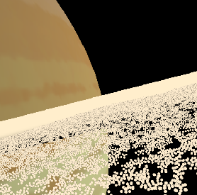
Saturn's ringsA simulation of Saturn's rings --- a few thousand particles are simulated, in a repeating tiled region. You use the mouse and keys to fly in it. |
© Hugo2015. Session @sessionNumber